
Introduction
I tried to reproduce the Agent Dissolve Effect with Cubes in the Matrix Demo of UE5.
Actually, the mechanism of the effect is explained in The Matrix Awakens: Creating the Vehicles and VFX | Tech Talk | State of Unreal 2022. So I would like to reproduce it based on this.
I provide the Niagara data that implements what I explain here and two samples of the effect, so if you want actual working data right away, please check it out.
https://heyyohanashima.gumroad.com/l/mwyfs
Version
Unreal Engine 5.1.0
Explanation of implementation
Summary
A brief description of how it works would be as follows.
- Overlap two target meshes
- Set a Stencil Value on one mesh
- Dissolve the target mesh. When doing so, the one with the Stencil Value should be dissolved with a slight delay.
- In Niagara, spawn particles in the bounding box of the target in screen space
- Keep alive particles that have the same stencil value in the screen coordinates as the target mesh’s.
Since the mechanism itself is same, I will first explain the implementation of the following simple example.
Dissolve Mesh and Stencil Value
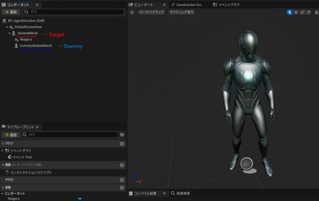
In a Blueprint, set a target mesh and place a dummy mesh (same mesh of the target) for stencil value.
You can make the dummy a little smaller with minus offset to normal direction by World Position Offset in material, to prevent Z-Fighting.
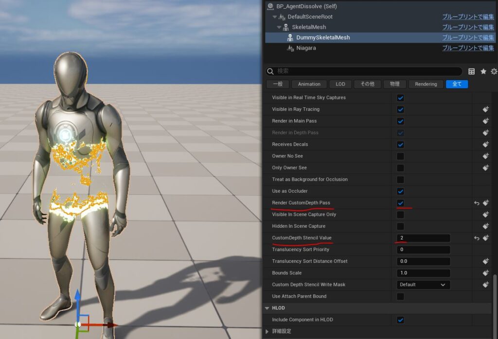
Then, Render CustomDepth Pass is turned on and CustomDepth Stencil Value is set to 2 this time (this value is used in Niagara, but the value itself can be anything).
Also, since we do not want the Stencil Value to be written where it is covered by the target mesh, we turn on the Render CustomDepth Pass for the target mesh as well.
This dissolve effect itself is not explained in detail because it is out of range of the theme of this article.
But to put it briefly, it is like animating a threshold to make the target mesh disappear based on the distance from a certain position with noise and edge emissive.
Then, the dummy mesh is also dissolved but with a slight delay from the target mesh, so that Stencil Value is written in Stencil Buffer like below.

We will use this stencil value area to filter particles later, but before proceeding to that step, I will explain the process of spawning particles on the screen space bounding box of the target mesh.
Spawn particles on the screen space bounding box of the target Mesh in Niagara
※ For some reason, the processing of Niagara’s ScreenSpace⇔WorldPosition coordinate conversion system did not behave as I expected, so I implemented it in my own way, which is a bit of a roundabout way. I don’t know if it is my lack of understanding or a bug in UE5, but there may be a better way, so please take this as just an example 🙂
The Niagara Eimitter’s overall picture is below. ※ Must be GPU Sim as it reads GBuffer.
The modules circled in red do the process of spawning particles on a screen space bounding box, which is implemented by Niagara Module Script.
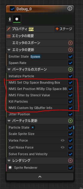
NMS Set Clip Space Bounding Box and NMS Get Position WSBy Clip Space BB are the modules to calculate a screen space bounding box of a given mesh. Let’s take a look at each of them.
NMS Set Clip Space Bounding Box
Here, the 2D bounding box in the screen space is calculated from the 3D bounding box of the target mesh in the world space.
To do this, we need to send the bounding box information of the target mesh to Niagara.
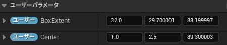
First, create a user parameter for Niagara.
- BoxExtent: Size of the bounding box of a mesh (distance from the center to each face, so half size of the box)
- Center: Center of the bounding box of a mesh
Then, send the information to Niagara for every frame like below.
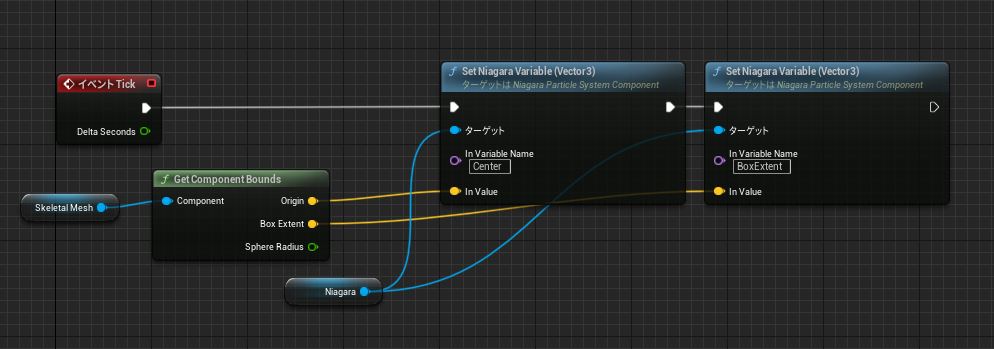
The following is the content of NMS Set Clip Space Bounding Box . The bounding box information sent from BP is set as input values for CenterWS and HalfExtentWS.
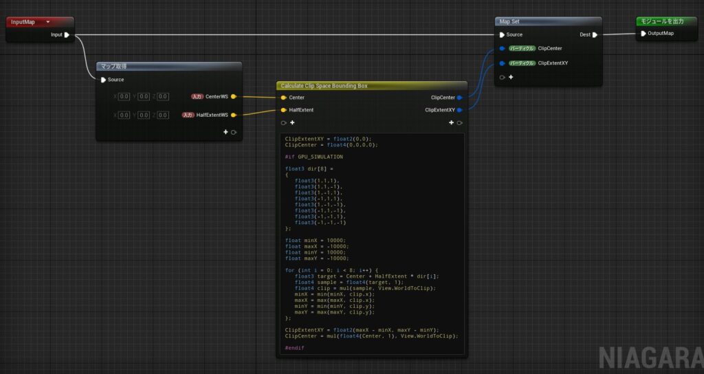
The bounding box calculation for screen space is written in HLSL. (To be more precise, the calculation was done in clip space because for some reason it did not work in screen space)
The plan is to get the coordinates of the 8 vertices of the 3D bounding box on the screen space, and then take the min-max of x,y as the screen space bounding box (this method is not necessarily an accurate calculation, but it looks OK, so I’m OK with it)
// Outputs
ClipExtentXY = float2(0,0);
ClipCenter = float4(0,0,0,0);

#if GPU_SIMULATION

// Prepare direction vectors to each vertices in array to calculate efficiently
float3 dir[8] =
{
   float3(1,1,1),
   float3(1,1,-1),
   float3(1,-1,1),
   float3(-1,1,1),
   float3(1,-1,-1),
   float3(-1,1,-1),
   float3(-1,-1,1),
   float3(-1,-1,-1)
};

// Variable for min and max of x, y value in clip space coordinate
float minX = 10000;
float maxX = -10000;
float minY = 10000;
float maxY = -10000;

for (int i = 0; i < 8; i++) {
   float3 target = Center + HalfExtent * dir[i]; // Calculate position of vertices of boundingbox in world space
   float4 sample = float4(target, 1);
   float4 clip = mul(sample, View.WorldToClip); // Transform from world to clip space
   minX = min(minX, clip.x);
   maxX = max(maxX, clip.x);
   minY = min(minY, clip.y);
   maxY = max(maxY, clip.y);
};

// Set the value of size and center position of bounding box
ClipExtentXY = float2(maxX - minX, maxY - minY);
ClipCenter = mul(float4(Center, 1), View.WorldToClip);

#endif
The outputs of this module are two.
- ClipExtentXY: Size of the bounding box in clip space (Vector2)
- ClipCenter: Center of the bounding box in clip space (Vector4: Since depth information z of the center of the target Mesh and w value used for coordinate transformation are needed)
This information is used to control the position of Particle generation in the next module.
*In UE5.4, use View.TranslatedWorldToClip instead of View.WorldToClip.
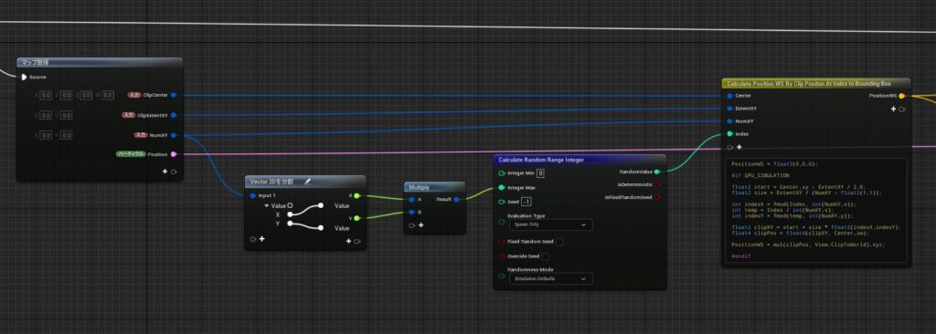
NMS Get Position WSBy Clip Space BB
What this module does is select an arbitrary point for each particle within the bounding box in screen space obtained, convert it back to world coordinates, and move the particle to that position.
The inputs to this module are as follows
- ClipCenter: Center of the bounding box in clip space obtained by NMS Set Clip Space Bounding Box
- ClipExtentXY: Size of the bounding box in clip space obtained by NMS Set Clip Space Bounding Box
- NumXY: The number of bounding box divisions for finding an arbitrary point
- Write to Position: Flag to indicate whether the position obtained is actually applied to the Particle
Changing NumXY changes the density of Particle alignment as shown below.
First, each particle is given a random value among the total number of divisions (9600 if X=60, Y=160).
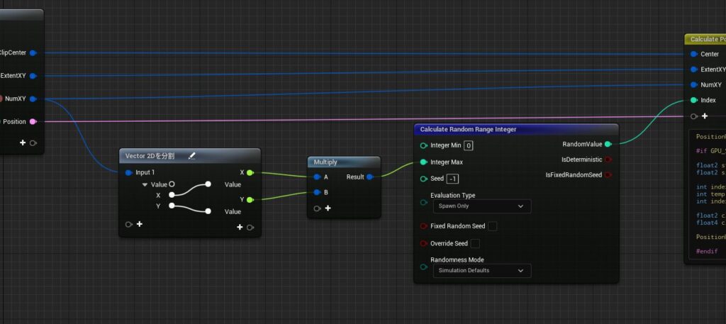
Using the values, the process of calculating the points on the bounding box in screen space and converting them to world coordinates is written in HLSL.
// Outputs
PositionWS = float3(0,0,0);

#if GPU_SIMULATION

float2 start = Center.xy - ExtentXY / 2.0; // Calculate position of right corner in clip space as base position
float2 size = ExtentXY / (NumXY - float2(1,1)); // Calculate delta distance of divisions

// Calculate index of point by the given random number
int indexX = fmod(Index, int(NumXY.x));
int temp = Index / int(NumXY.x);
int indexY = fmod(temp, int(NumXY.y));

// Calculate position in clip space by the index of point
float2 clipXY = start + size * float2(indexX,indexY);
float4 clipPos = float4(clipXY, Center.zw);

// Transform the position into world space coordinate by zw value of center position of target mesh in clip space
PositionWS = mul(clipPos, View.ClipToWorld).xyz;

#endif
*In UE5.4, use View.ClipToTranslatedWorld instead of View.ClipToWorld.
Filter Particle by Stencil Value
Now that we have generated a particle on the screen space bounding box of the target mesh, all that remains is to read the GBuffer’s Stencil Value by screen space position and perform filter processing.
This process is performed by the module NMS Filter by Stencil Value
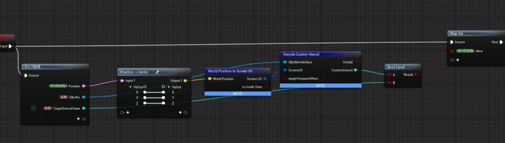
It simply converts the world position to screen UV, reads the Stencil Value, and sets an alive attribute if it matches the Stencil Value given as input. The processing nodes are all provided by Niagara in default.
※ You might think that why not using World Position to Screen UV for the process so far. But It doesn’t work as I expected when transforming from screen uv to world position, so I have no choice but to use clip space instead of screen space. I have heard that UE Eidotor’s calculation around the screen is a little peculiar (it calculates the entire Editor window as the screen, not just the area actually displayed. And I assume there are a lot of changes in UE5…), so you may need to read the engine code to understand this area.
All that remains is to determine whether to Kill or not with the Alive attribute created here.
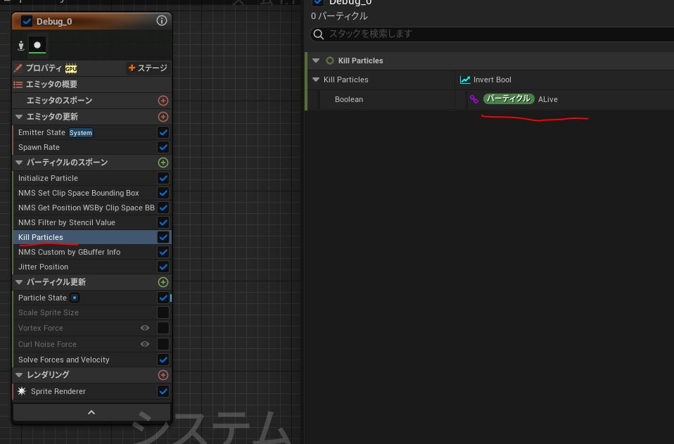
You can see that the Particle remains only at the edge (Stencil Value=2).
Attach a Particle to a Mesh using CustomDepth
Currently, the Particle is positioned perpendicular to the camera based on the depth of the center of the Mesh’s bounding box. In this sample, there was no major visual problem even with the current arrangement, but to make it more accurate, the Particle should be properly attached to the target Mesh.
As with Stencil Value, the Custom Depth value is read from the GBuffer and the Particle is attached based on the depth information of the Mesh.
I have written an explanation of this area below, so I will skip it this time.
【UE4.26】Niagara Advanced 解説基礎編~Sample GBuffer Attributes~
Bonus: Sample Scene Color
In the same way, read the Scene Color from the GBuffer and reflect it in the particle’s color. Now, simply changing the dissolving color on the material of the mesh will also change the Particle’s color automatically.
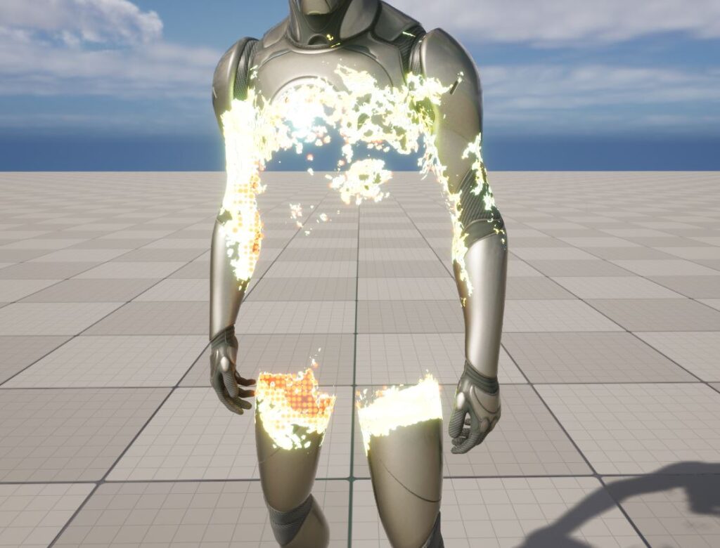
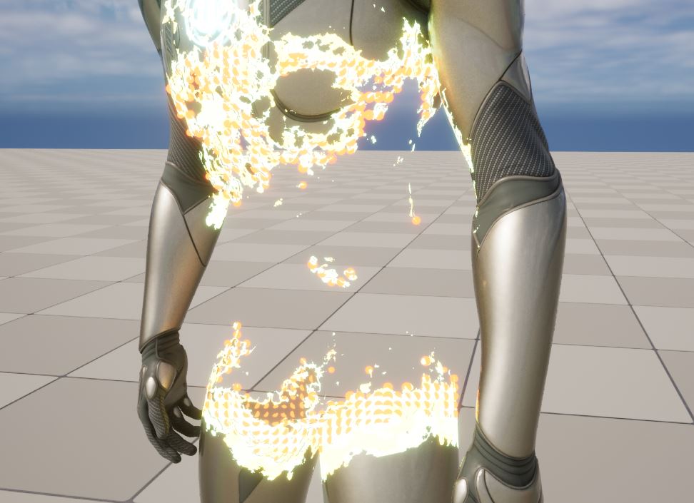
Matrix Demo-like
This is the end of the explanation of the implementation itself, but I will show you a little bit of the Matrix Demo
Yeah I know it’s not as good as the demo… It’s simply because the mesh is different from the original, there is no same animation, and there is not enough time…, but I think the mechanism is almost the same. You can see it just as an example of my work.
The mechanism is exactly the same as the simple sample I explained above, with the only difference being that particles are cubes, and collision is given.
Conclusion
When I saw the Matrix Demo, I found it very cool and opened City Sample with great enthusiasm, but I could not find any data for this expression…
Then the instructional video came out and I learned how it works, so I implemented it immediately.
It is not impossible to create particles along a Mesh Dissolve by spawning particles simply from a mesh, and I have used it sometimes, including in my work.
However. I have to implement a process of dissolving both in Material and in Niagara, and it`s quite difficult to control the way Particles appeared depending on the Vertex density of the Mesh, so learning how to do it in the screen space was an eye-opener!
Reading GBuffer in Niagara is still an experimental feature, but I haven’t encountered any major problems so far, so I think it can be used for video purposes at work as well!
I like Niagara!


