Introduction
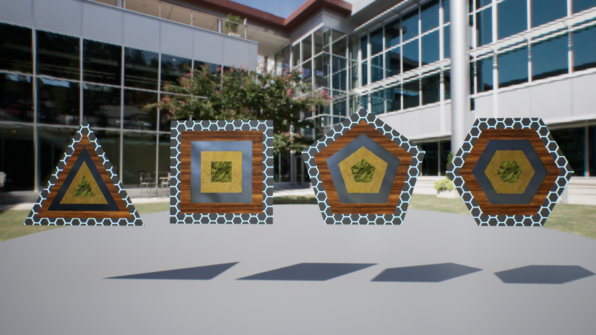
I will explain a shader that can procedurally draw regular polygons, like in the video above.
I take UE5 material as an example for the implementation of this shader, but the logic itself is basically written in HLSL, so it can be easily reproduced in Unity or GLSL or anything.
I assume that there are some ways to procedurally draw polygons, but I personally like this method because it is a fairly concise logic, even though there are aspects that limit it to regular polygons.
I offer, in the below link, this UE5 material and some material instances for some variations like a stripe pattern shown later, so you can check it out if you want directly the data itself.
https://heyyohanashima.gumroad.com/l/nmusq
Explanation of the shader
Overall Picture
The overall picture of the part that draws regular polygons looks like this.
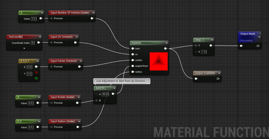
Most of the processing, however, is implemented in the Custom node using HLSL, so I will explain this while showing the code, but first, I will explain the concept.
Create a gradation
This method calculates the gradient from the center to each side to creat a regular polygon mask.
Create a gradient, from 0 to 1, from the center to each side, and erase (make transparent) the area beyond 1 to create a mask for each regular polygon.
The nice thing about gradients is that they can be used not only to create a mask but also for coloring and fading, which broadens their use.
How to get the gradients
This section explains how to create a gradation from the center to each side.
The key is the ‘dot product’.
When dot product is discussed in the context of computer graphics, it is often used to find the angle formed by two vectors. But there are other important usages of dot product.
Review of inner product
There are two properties of dot products that I often use myself in CG-related work.
① Angle formed by two vectors
② Length of the production vector
Both properties come from the mathematical definition of dot product, but since I won’t explain the formulas here, I will give a brief explanation using diagrams.
The first part is used in Fresnel calculations, or simple diffuse and specular reflection calculations in shader-related applications, and is probably a topic that comes up frequently, so I will not explain it here.
② is the nature that will be used in this project.
The term ‘production vector’ sounds a bit difficult, but it is easier to understand if you look at the diagram.
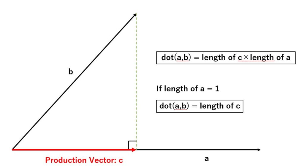
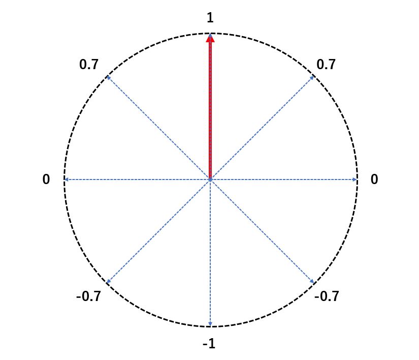
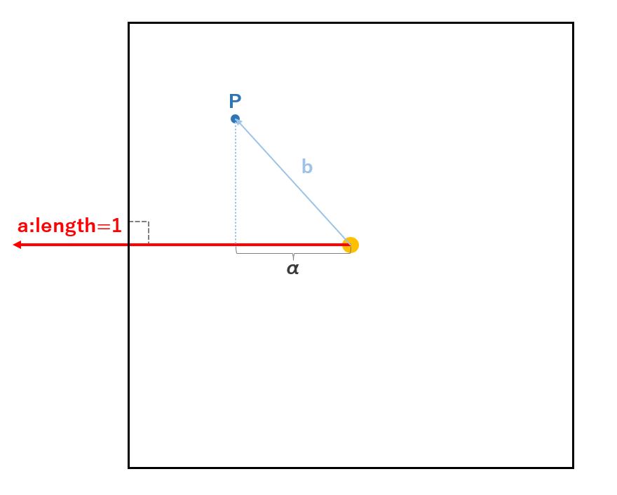
As shown in the figure above, when there are two vectors (a, b) starting from a point and you draw a line perpendicularly from the end point of one vector (b) to the other vector (a), the vector from the starting point to its intersection is called ‘production vector’ (c).
The dot product of a and b is the product of the length of the production vector c and the length of vector a.
By setting the length of vector a to 1, you can get the length between the intersection and the starting point (= length of the production vector), since multiplying by 1 by whatever does not change the value.
This property can be used to calculate the gradient from the center to each side of a regular polygon.
In addition, the value will be negative for the following vector positional relationships.
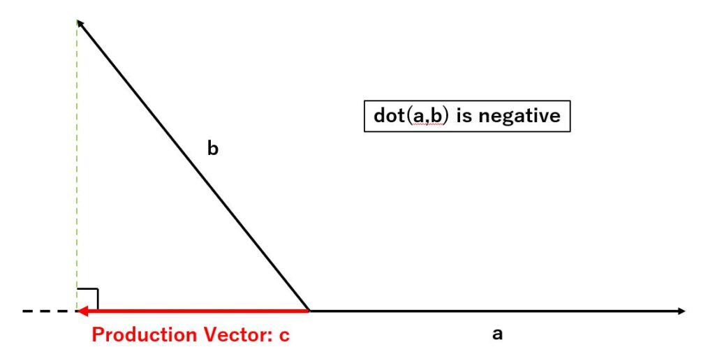
Incidentally, the positive projection vector itself can also be obtained by multiplying with vector a. This can be used when you want to cancel vector components in a specific direction, so it is good to keep this in mind.
Explanation of the specific method
First, let us take an equilateral triangle as an example.
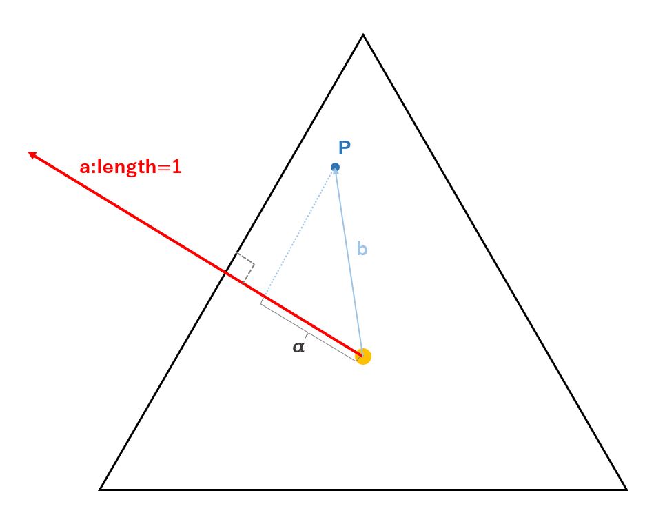
From the center of an equilateral triangle, find a vector (a) of length 1 perpendicular to the sides.
Next, find the vector (b) from the center of the equilateral triangle to any point (P).
By computing the dot product of these a and b vectors, we can find the length of the production vector of vector b (= length of α).
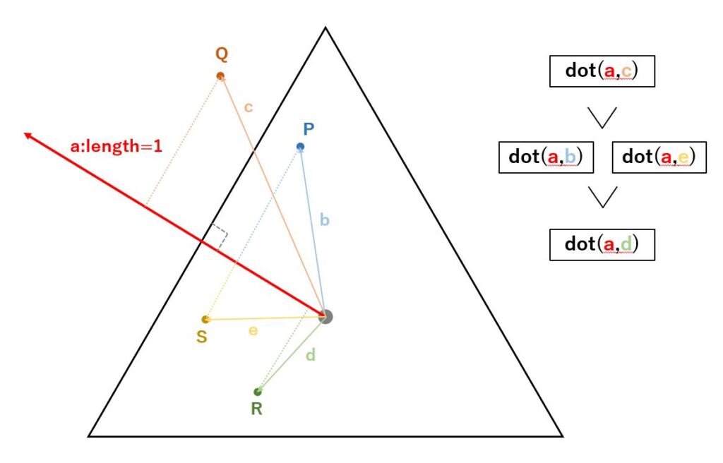
Similarly, by following the same procedure for arbitrary points Q, R, and S, we can see that the farther each point is from the center to the side direction, the larger the value becomes, and the closer to the center side, the smaller the value becomes.
We also see that points on a line parallel to a side, such as P and S, have the same production vector length.
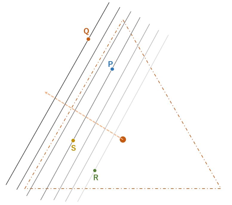
Thus, by computing the dot product, a gradient parallel to a side can be obtained.
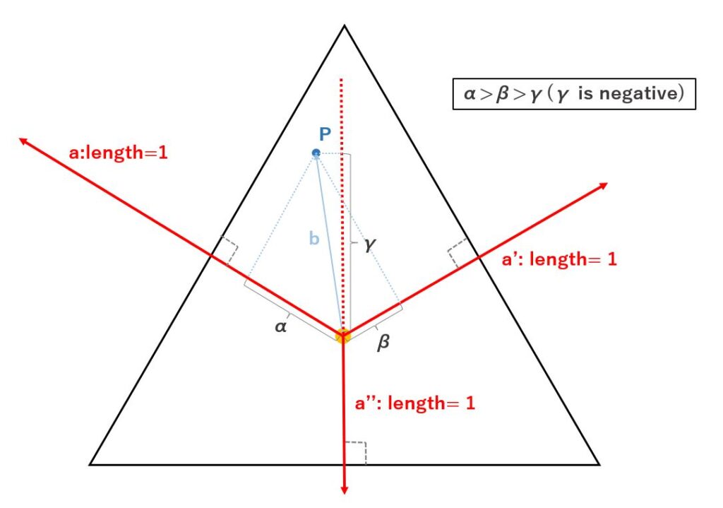
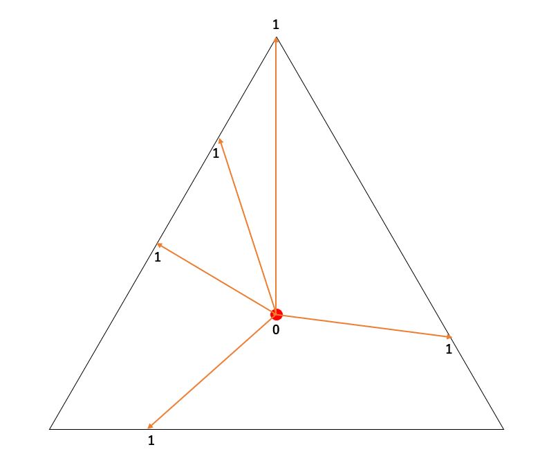
In addition, for an equilateral triangle, three perpendicular lines (a, a’, a”) can be drawn from the center to each side. As shown in the figure above, the dot product obtained with the perpendicular vector drawn to the nearest side of its own point is always the largest value. In an implementation, you can find the dot product of the three vectors and use the largest value as the gradient for that point.
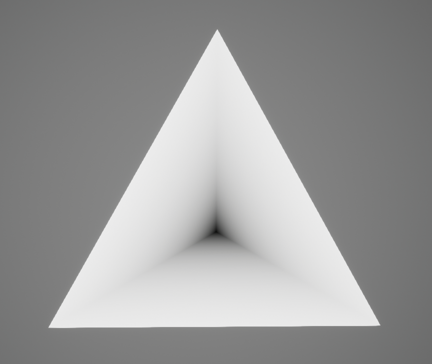
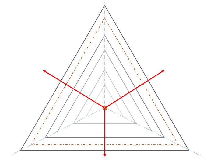
By doing so, a gradient parallel to each side can be obtained for all sides as shown below.
The same idea can be used to obtain a gradation in the case of a rectangle.
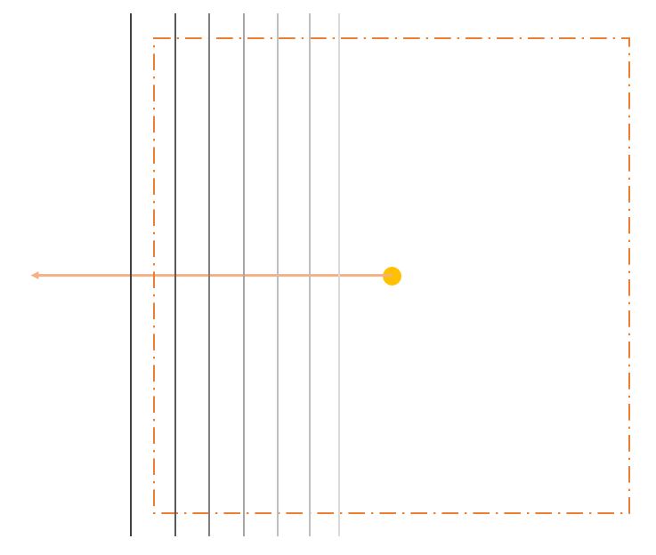
And the same logic can be used to obtain the gradient for all regular polygons.
Finally, we summarize the steps to get the gradient.
- Find a vector of length 1 perpendicular to each side from the center
- Take the dot product of a vector from the center to any point and the vector of Step 1
- Take the highest value in Step 2 as the gradient value for that point.
- Divide the value of Step 3 by the distance from the center to the side and normalize (0~1)
Explanation of implementation code
Now, I will start to explain the actual HLSL code
First, I will show the full text of the code.
const float DEG_TO_RAD = 0.0174533;
int _num = max(num, 3); // Make sure more than 3 vertices

float _deltaAngle = 360.0 / (float)_num;
float2 _dir = uv - center;

float _gradAlongMedian = 0;

// Repeat calculation _num times and get max value of dot product
for(int i = 0; i < _num; i++) {
   float _degree = angleOffset + _deltaAngle * i;
   float _x = cos(_degree * DEG_TO_RAD);
   float _y = sin(_degree * DEG_TO_RAD);
   float2 _medianDir = normalize(float2(_x,_y));
   _gradAlongMedian = max(dot(_medianDir, _dir), _gradAlongMedian);
}

float _centerToSideLength = radius * cos(_deltaAngle * 0.5 * DEG_TO_RAD);
float _normalizedMedianGradation = _gradAlongMedian / _centerToSideLength;

return _normalizedMedianGradation;
The five inputs are as follows.
- num:Number of vertices
- uv:Coordinate system for drawing regular polygons
- center:Center of regular polygons in the coordinate
- angleOffset:Offset of regular polygon orientation
- radius:Size of regular polygon (length from center to vertex)
The output returns a gradient from the center to each side.
float _gradAlongMedian = 0;

// Repeat calculation _num times and get max value of dot product
for(int i = 0; i < _num; i++) {
   float _degree = angleOffset + _deltaAngle * i;
   float _x = cos(_degree * DEG_TO_RAD);
   float _y = sin(_degree * DEG_TO_RAD);
   float2 _medianDir = normalize(float2(_x,_y));
   _gradAlongMedian = max(dot(_medianDir, _dir), _gradAlongMedian);
}
Here, the dot product is calculated for the number of vertices (= number of sides) and the maximum value is stored in _gradAlongMedian.
The vector of perpendicular lines from the center to each side is calculated by trigonometric functions. Each angle can be calculated by first dividing 360 by the number of vertices and adding the delta angles in each repetition.
float _centerToSideLength = radius * cos(_deltaAngle * 0.5 * DEG_TO_RAD);
float _normalizedMedianGradation = _gradAlongMedian / _centerToSideLength;
The length from the center to the side is obtained by multiplying the length from the center to the vertex by cos(360/(number of vertices x 2)). Then, divide _gradAlongMedian to normalize.
Now we have a gradient that goes from 0 to 1 from the center to each side, and the points with _normalizedMedianGradation>1 will be located outside of the regular polygon.
Use gradients
Masking
As mentioned above, we have created a gradient such that the outer points are larger than 1. Using step function, we can create a regular polygon mask by erasing the points larger than 1.
Add color, Make stripes
Since gradient information is available, coloring can be done in any way. Stripes can also be easily created using fmod function, etc. although details are beyond the scope of this article.
Lastly
I had the opportunity to do some motion graphic work in UE at work, and I wanted to easily play with the size and rotation of primitive shapes, which led me to create this shader.
After all, it feels good to be able to create something generic with clean logic. It is also nice to realize a use for mathematical knowledge that you did not know before. I will keep exploring more hidden uses of math for CG!


