
Introduction
The following article, previously explained, deformed Static Mesh.
In this article, I will explain how to run a fake soft body simulation on a Skeletal Mesh that is being animated. But the mechanism itself is the same as with Static Mesh, so I will focus on the additional implementation for Skeletal Mesh.
Also, sample data implementing what is explained here is provided below, so if you want actual working data right away, please check it out.
https://heyyohanashima.gumroad.com/l/gmgmhl
Version
Unreal Engine 5.2.0
Summary
This article will explain the implementation of fake soft body simulation on an animated skeletal mesh like the deforming running Greyman as shown in the video above.
The only major difference from Static Mesh implementation is that the vertices of the Skeletal Mesh need to be sampled every frame, and then the settings can be adjusted accordingly.
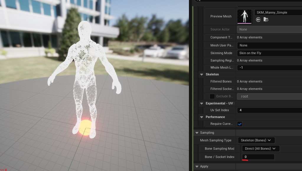
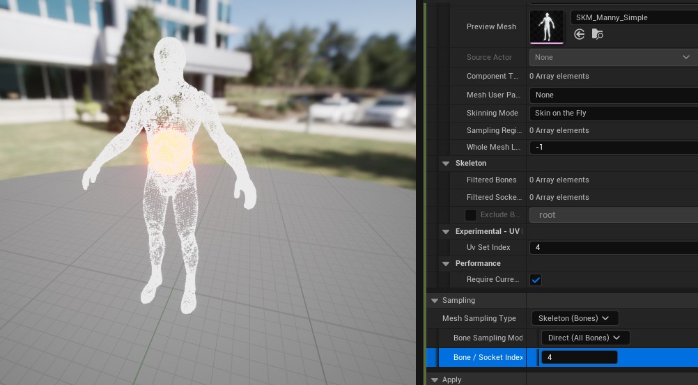
Also, the red circle in the second half of the video is the pivot point (starting point of the constraint) when calculating the Fake Soft Body Simulation.
You can see that as the pivot point changes, the deformation changes as well. I will explain this too in this article (by the way, the pivot point can be freely adjusted even in Static Mesh).
Preparation
The first important thing to do is to make sure that the UVs do not overlap.
Greyman’s default UVs do overlap as follows.
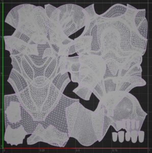
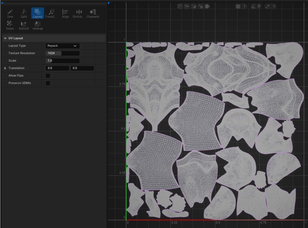
In that case, you can reapply the UVs in any DCC tool (you could also put them in other uv channel like UV1), or you can try using UE’s UV Editor for ease.
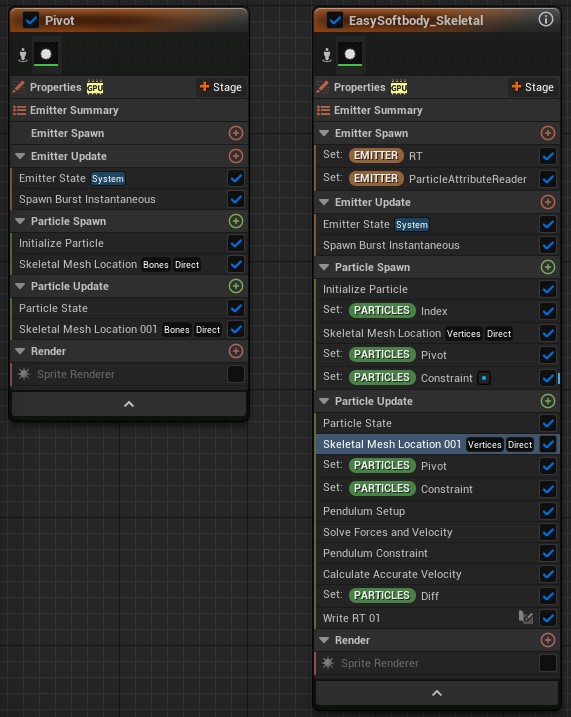
Sampling the Skeletal Mesh vertices in every frame
First, to sample the vertices of the Skeletal Mesh, use the Skeletal Mesh Location module.
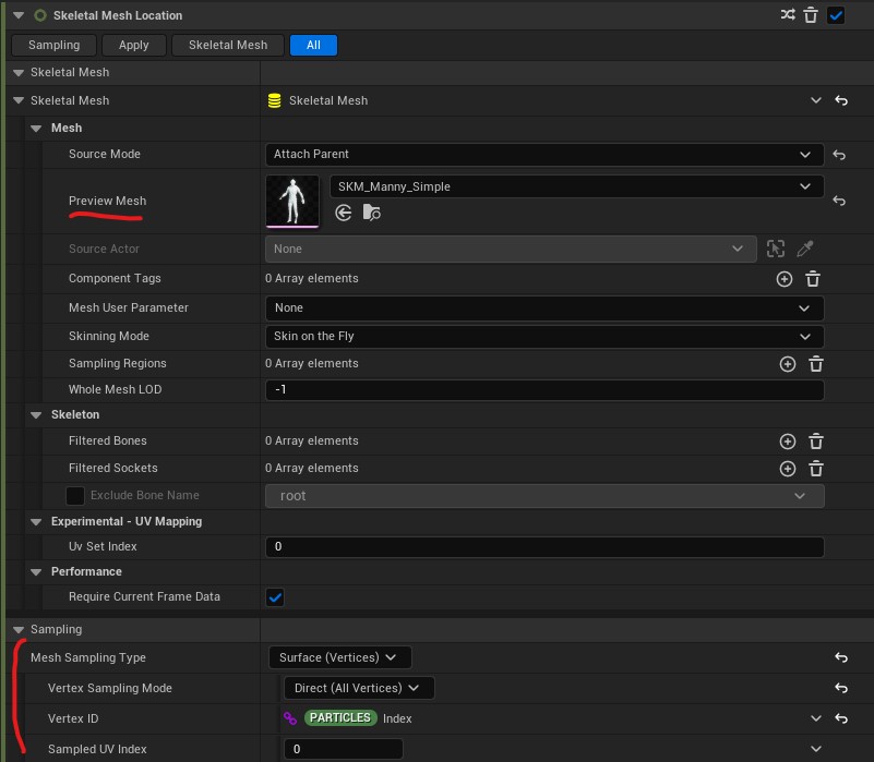
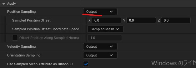
Put any skeletal mesh in the Preview Mesh and set the items under Sampling as shown in the image above.
(If you wish to use a UV other than UV0 for subsequent writing to the Render Texture, set the Sampled UV Index to the corresponding number of your UV index)
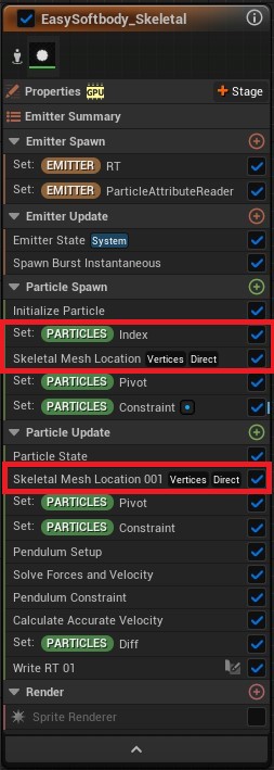
Here, the Index parameter set for Vertex ID is a parameter that I created myself to store the Execution Index.

The reason why this parameter is created is that when Return Exec Index is used in Particle Update, the Index value is not consistent and different values are returned for the same Particle in each frame.
Therefore, the Execution Index can be stored as a parameter in the Particle Spawn, and when sampling vertices using Skeletal Mesh Location in Particle Spawn and Particle Update, the Vertex ID can be specified in that parameter. This allows the same Particle to sample the same vertex every frame.
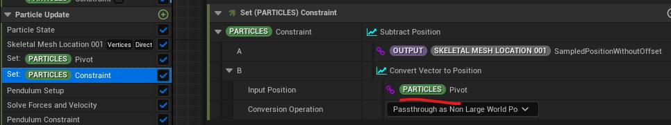
Finally, in Skeletal Mesh Location within Particle Update, change Position Sampling to Output. If this is set to Apply (Rigid) which is by Default, the Particle will be stuck to the Mesh surface at this time and deformation will not work correctly. The position of the Skeletal Mesh vertices should only be used for calculations and should not override the actual Particle’s position.
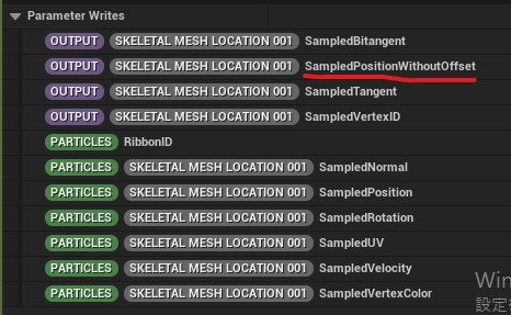
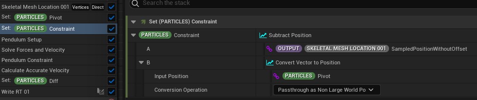
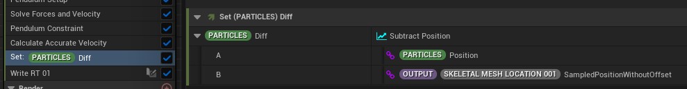
The position of each vertex sampled by this is stored in SampledPositionWithoutOffset. This is used for Constraint and Diff calculations like below.
Setting the pivot point
As briefly explained in the article on Static Mesh, the Fake Soft Body Simulation described here works with a simple PBD that uses a Constraint as a vector from an arbitrary point to each Particle.
This arbitrary point was set to the origin of the Niagara System in the previous article, but this can be set anywhere you like.
So this time, I implemented that it can be set at any bone position in the Skeletal Mesh.
This is the process.
- Place one Particle at any bone position in the Skeletal Mesh (Pivot Emitter)
- Read the particle placed in step 1 by Particle Attribute Reader and use its position as the starting point of Constraint.
Place a particle at any bone position in the Skeletal Mesh.
The Skeletal Mesh Location module allows sampling of bones as well as vertices.
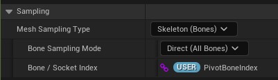
Any bone can be sampled by specifying the Index of the Bone in Bone / Socket Index.
Read by Particle Attribute Reader and use its position as the starting point of Constraint
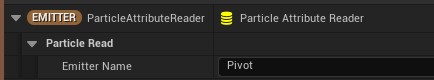
Particle Attribute Reader is a convenient function that allows you to read the Particle information of any Emitter.
At this time, Specify `Pivot` in Emitter Name.
Next, the Particle Attribute Reader is used to obtain the position of the Particle at the desired bone position and store it in the parameter Pivot.

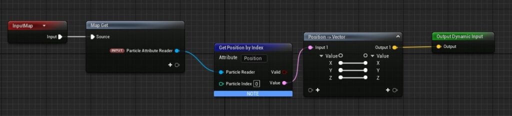
I simply use the Particle Attribute Reader to read the Position.
Since there is only one Particle emitted by Pivot Emitter, you can refer to that Particle by putting 0 in the Particle Index of Get Position by Index.
The rest of the time, this Pivot parameter is used to calculate Constraints.
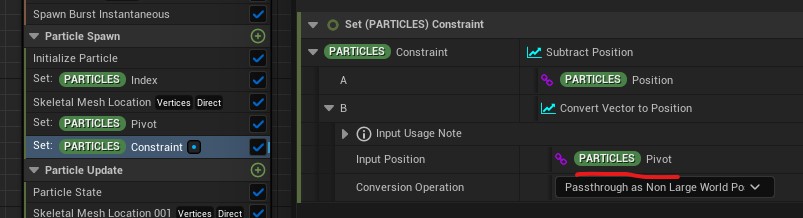
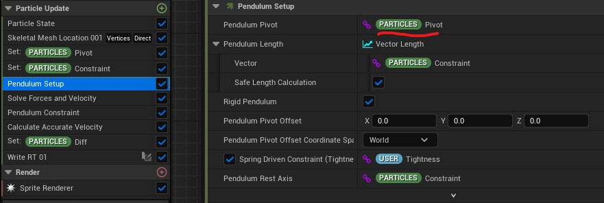
Pivot parameter is also specified for Pendulum Pivot in Pendulum Setup.
Now, place the Skeletal Mesh on a level and put this Fake Soft Body Simulation Niagara System in its child.
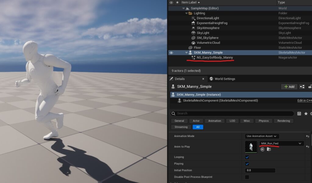
Then, set the Animation and play. You can run a fake soft body simulation on the Animated Skeletal Mesh!
Supplement
In the default state of UE5.2.0, the display around shadows is not correct, so I will add how to fix that.
Influence of Virtual Shadow Maps
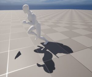
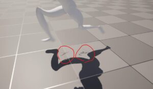
When actually playing with this sample, a phenomenon occurs in which shadows appear to be left behind.
This is due to the new Virtual Shadow Maps feature in UE5, which caches shadows and draws shadows from cache for areas where there is no motion.
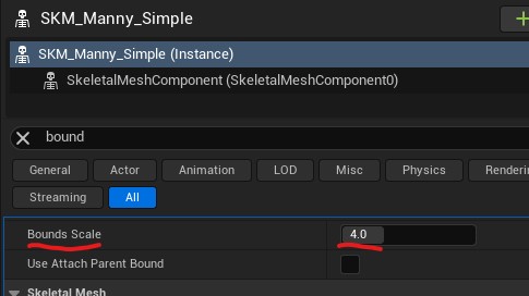
I do not know the details of how this motionless area is calculated, but it is certain that the Bounds of the mesh is involved, so by increasing the Scale of the Bounds, we can make sure that the shadow cast by the deformation is properly updated each frame.
Anti-aliasing effects
In UE5, TSR anti-aliasing is set by default. This can cause jaggedness in the trajectory of fast moving objects, and this has caused some strange marks in the shadow areas.
I think there are some more fine-tuning of TSR settings in this area, but for a quick fix, go to Project Settings and change the Anti-Aliasing Method to TAA or FXAA.
Bonus
If you want to deform only a part of Mesh, I think the following policy is the way to do it.
- Weighting the Particle placed at each vertex in the Niagara System and adjusting the Tightness value for each Particle.
- Create a Mask in the Material and adjust the strength of the World Position Offset.
In either method, I think the key is how to create the mask. You can create a mask with a Texture, use Vertex Color, or create a mask with a node in the Material.
The sample data provided below includes a sample of creating a mask within a material to adjust the strength of the World Position Offset like the post below, so check it out if you are interested!
https://heyyohanashima.gumroad.com/l/gmgmhl


