
Introduction
The VFX explained here is inspired by one of Keijiro’s works, which implements cool deforming character visual effects with Geometry Shader in Unity.
I also imitated those works in Unity before like below.
https://github.com/YoHana19/VoxelSizeAnimation
https://github.com/YoHana19/VoxelTeleporter
https://github.com/YoHana19/VoxelTeleporter2
https://github.com/YoHana19/Bandlizer
This time, I decided to reproduce them with Houdini and created the first three effects listed above.
アドベントカレンダー用①
— HeyYo (@yo_hanashima) December 17, 2021
Keijiro神の作例をHoudiniで再現#Houdini pic.twitter.com/gzYylIdSZz
アドベントカレンダー用②
— HeyYo (@yo_hanashima) December 17, 2021
Keijiro神の作例をHoudiniで再現#Houdini pic.twitter.com/o3X56orD9F
アドベントカレンダー用③
— HeyYo (@yo_hanashima) December 18, 2021
Keijiro神の作例をHoudiniで再現#Houdini pic.twitter.com/qDJeDYTudP
The actual working data is also available for purchase here, so feel free to check it out if you’re interested.
https://heyyohanashima.gumroad.com/l/svdbo
Overview
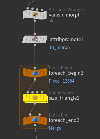
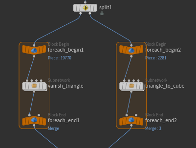
The concept behind the creation process for all the examples listed above is the same: it involves processing the triangular polygons that make up the geometry using a foreach loop, transforming them into shapes like squares, cubes, etc., one by one.
At this stage, we make the size, center position, and deformation timing customizable for each primitive from the outside to create variations.
So, I’ll first explain the common transformation process for a single triangular polygon geometry before delving into each example.
Transformation Process From Single Polygon
There are three types of transformations: triangle transformation, square transformation, and cube transformation. The triangle transformation only alters the size of the triangular shape. In this example, about 90% of the polygons simply shrink or enlarge and disappear or reappear. If all polygons were transformed into squares or cubes, the result would be a cluttered mess that’s hard to see.
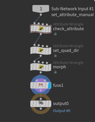
These transformation processes are used in the actual examples, so I’ve encapsulated them into a subnetwork.
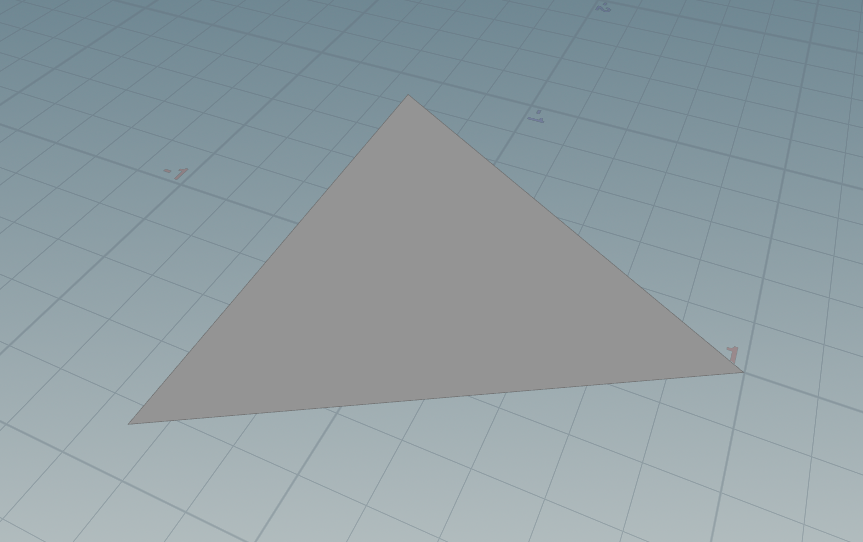
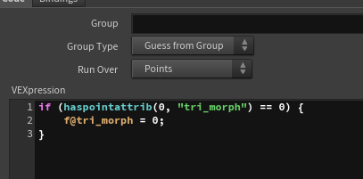
Triangle Transformation
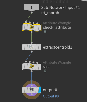
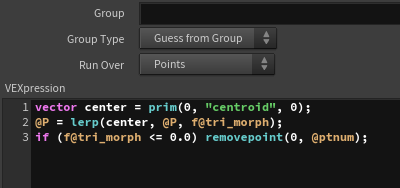
First, I check if the necessary attributes are present. The tri_morph attribute controls the distance of each vertex from the center of the polygon, which in turn controls the size of the triangular polygon.
Using the “Extract Centroid” node, I store the centroid (the center of the polygon) in an attribute named centroid.
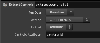
Then, by multiplying the tri_morph value by the vector from the centroid to each vertex, the size is controlled. When the tri_morph value is 0, the polygon becomes a point, so it is deleted.
Square Transformation
This transformation is slightly customized to match the example. It is not entirely generalized. Specifically, the square shape is always aligned with the Y-axis, and the pivot and center positions are used to control the orientation of the face. More details follow.
First, I check the required attributes. The attributes used for control are below.
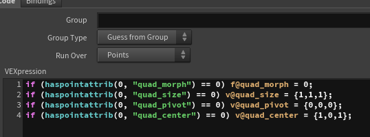
quad_size: The size of the square
quad_pivot: The starting point of the direction vector for the face
quad_center] The position of the center of the square
Next, I add one point and transform the polygon into a square by adding the new point to the polygon’s vertices. The position and UV values can be chosen arbitrarily. For this example, I added the point at the position of the second vertex and used the UV of the first vertex for the new square’s UV.
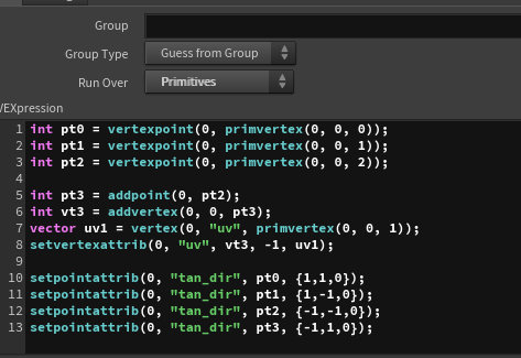
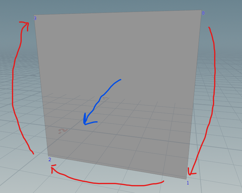
For each vertex, I decide the direction (in tangent space) from the center and store it in tan_dir. This can be chosen arbitrarily, but the key is ensuring that the vertices are ordered in a clockwise direction to maintain the correct orientation of the polygon.
I then proceed with the transformation. First, I compute the direction from the center to each vertex in world space (converting the tangent XYZ directions to world space).
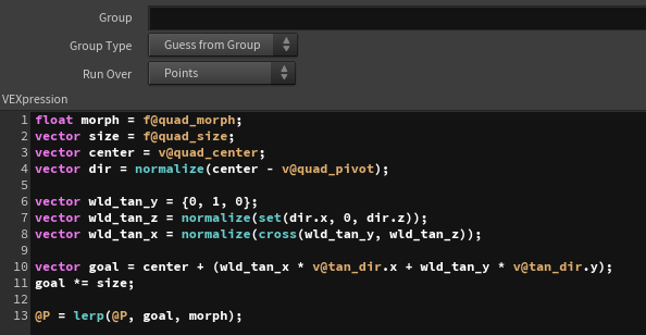
The tangent Y direction (wld_tan_y) is parallel to the Y-axis, so it is set to (0, 1, 0).
The tangent Z direction (wld_tan_z) is determined by the vector from the pivot to the center (ignoring the Y-axis since it must remain parallel to the Y-axis). This ensures the square faces outward from the pivot.
The tangent X direction (wld_tan_x) is calculated by taking the cross product of wld_tan_x and wld_tan_z.
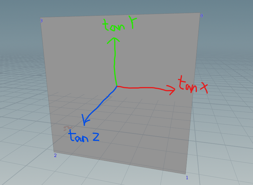
Using these results, I multiply the precomputed tan_dir by the vectors, add the center position, and compute the position of each vertex in world space. The size of the square can be controlled by multiplying the result by the size vector.
Finally, I interpolate between the original position and the square position to control the degree of transformation.
Afterward, I fuse any overlapping points to ensure clean geometry.
Cube Transformation
This process is a bit more complex, especially when it comes to matching up the newly created vertices with the original vertices.
First, I check the required attributes as same as others.
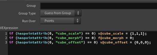
cube_morph: Controls the degree of transformation (0 = triangle, 1 = cube)
cube_offset: The offset from the center of the original polygon
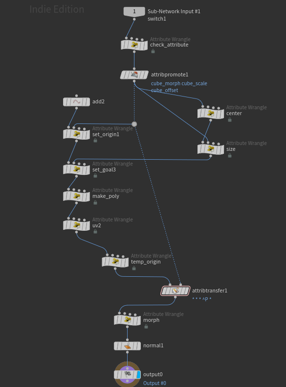
These attributes are moved into detail attributes, and the average distance from the center to each vertex is also stored in detail attributes to reflect the original polygon size to scale the cube after transformation.
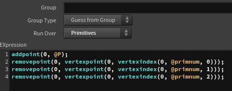
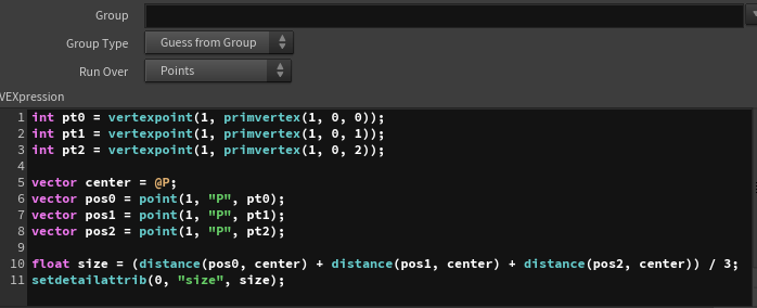
size attribute).Next, I will add 8 points using the “Add” node, set their original positions (corresponding to one of the vertices of the original triangular polygon) as well as their deformed positions, and create polygons for each face of the cube.
There are a couple of important considerations:
- Vertex Order: The direction of the polygon’s face is determined by the clockwise order of the vertices, so I must be careful to maintain the correct order when creating the polygons.
- Mapping Original to New Vertices: Each cube face must map to the original triangular vertices in such a way that all three vertices of the original triangle are included in each cube face.
今回は、下の写真になるように各種設定しました。
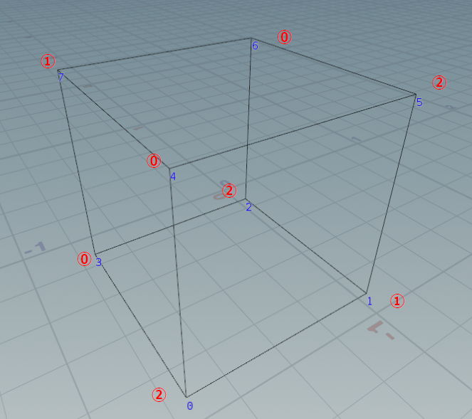
Red Number: Vertex Index of Original Polygon
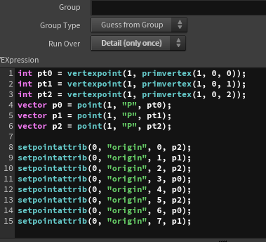
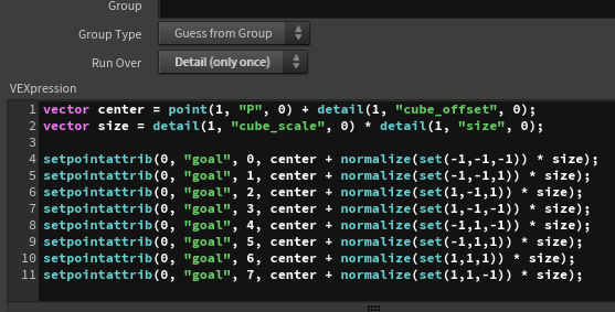
I create a origin attribute on the new vertices to store the positions of the original vertices. I then add the cube_offset to the center position and multiply the cube_scale by the size of the original polygon to determine the size of the cube.
The direction of each vertex from the center is calculated, scaled by the cube_scale, and added to the center to determine the final position of each vertex in the cube, which is stored as. goal attribute.
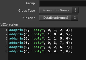
Finally, I select the vertices to create the cube faces, ensuring that the vertices are ordered in a clockwise direction for proper polygon orientation.
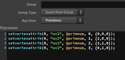
I also apply UV2 to each face of the cube to calculate emission mask later.
To transfer the attributes from the original polygon, I will first move each vertex to the origin position, then use attribute transfer to transfer the attributes. (This step is optional.)
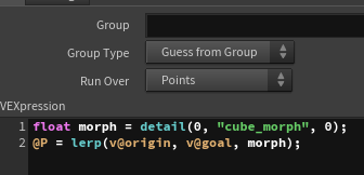
Finally, I will lerp the positions of the origin and goal using cube_morph to control the deformation.
Note that the cube transformation process may not be perfectly smooth in this approach, so there could be a better way to achieve smoother results.
With the explanation of the common transformation process complete, I will now move on to explaining each example. The focus will be on how to animate the parameters that can be controlled externally in the deformation process to achieve the effects seen in the examples.
Example1: Quad Teleport
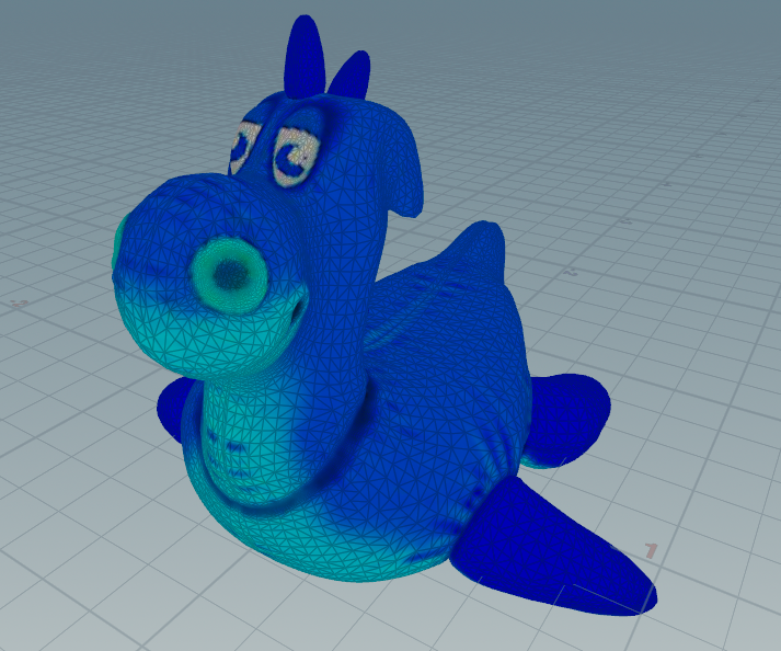
I’ll start with some preparation.
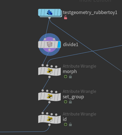
First, I divide the rubbertoy into triangular polygons.
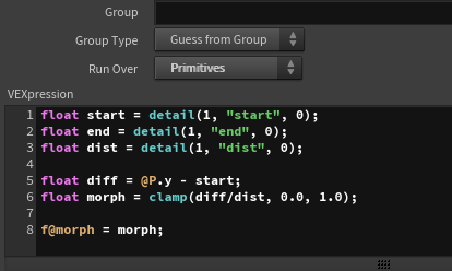
Next, I create a morph attribute, which will be used to control the degree of transformation during the deformation process.
This is done by animating two planes moving from top to bottom. When the y position of a primitive is between the two planes, the morph value changes from 0 to 1.
Therefore, when the lower plane passes, the effect starts (morph=0), and when the upper plane passes, it ends (morph=1).
The set_group node groups the triangles into two groups: one that shrinks and disappears and one that transforms into squares. Around 96% of the polygons will shrink and disappear.
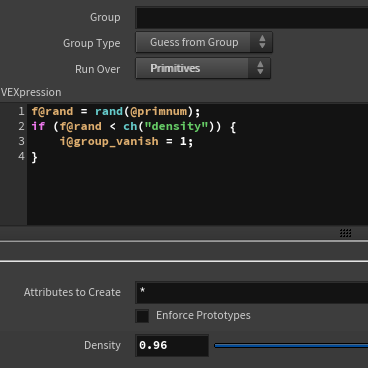
I’ll store the primnum as an id for convenience when applying colors or other attributes later.
Now, let’s move on to explaining the control of the deformation parameters.
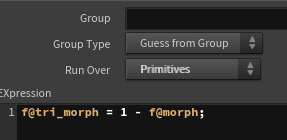
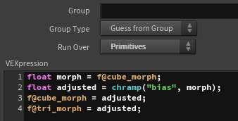
The triangle transformation is simple. I subtract the morph value from 1 and assign it to the tri_morph attribute to control the transformation for each primitive.
Next, for the square deformation, I’ve also included an effect at the beginning where the triangular polygon is expanded, so triangle deformation is used a little as well. I’ll explain everything step by step, including that.
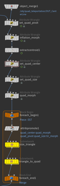
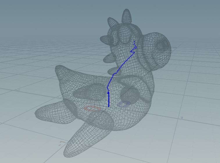
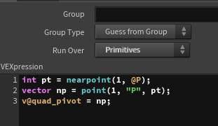
First, let’s control the quad_pivot. In this example, quad_pivot is used as the center point around which the square rotates. Since the rubbertoy model has a significantly different center point on the XZ plane for its top part, I use a plane animated for the morph effect to cut the rubbertoy, then calculate the center point for each frame and connect them into a line.
For this line, I perform a nearpoint operation on each primitive to determine the closest point’s position, which is then assigned to the quad_pivot.
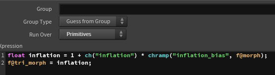
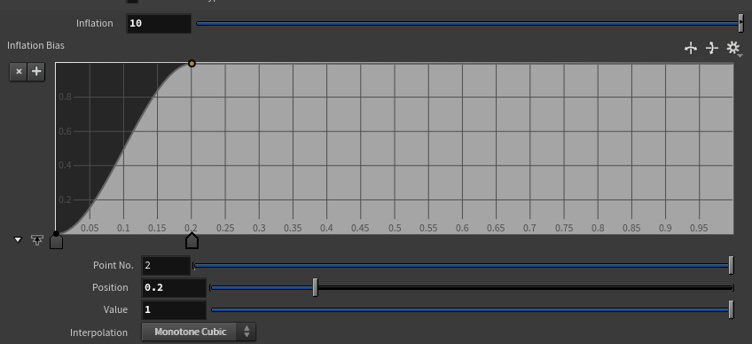
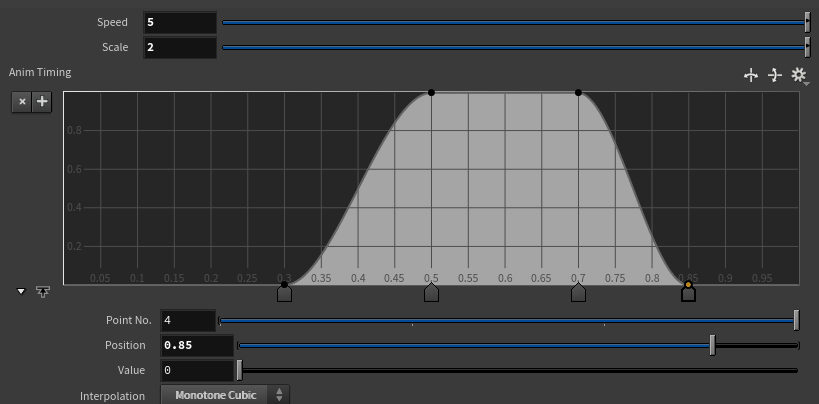
Next, to scale up the triangular polygon at the beginning, I set the value of tri_morph using inflation_morph. By controlling the ramp value, I create the initial expansion effect.
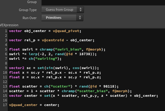
Then, using set_quad_center, I define the position of the square’s center, quad_center. I calculate vectors from the quad_pivot position to each primitive, and use the ramp-controlled morph value to rotate them. Additionally, I use the ramp-controlled morph value to control the distance from the quad_pivot, which animates quad_center moving away from the pivot while rotating in sync with the morph effect.
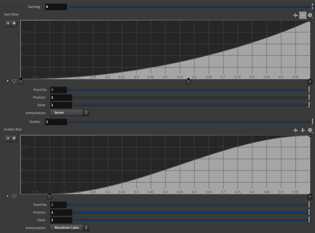
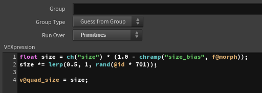
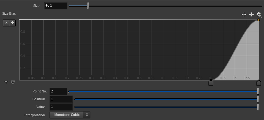
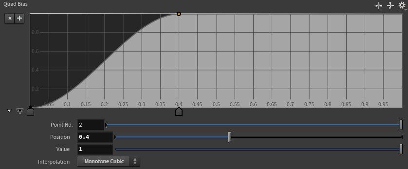
For quad_size, I control the ramp so that it ultimately reduces to 0, creating an animation where it disappears at the end.
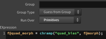
Finally, I control the value of quad_morph using the original morph value and the ramp, adjusting it so that the square transformation is completed around the middle of the animation.
With all the parameters set, I will now apply the triangle and square deformation processes to each primitive.
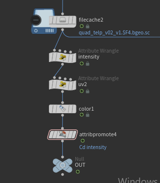
Since the deformation process can be heavy, I will cache it, and then adjust the look by setting necessary parameters like Color and Emission to match the morph values before finishing.
Example2: Voxel Animation
This example is quite simple, and since the control of the morph and the separation of triangle and cube deformations are almost the same as in Example 1, I will skip those details.
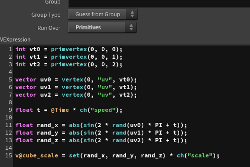
The key part is how to animate the cube_scale, so I will explain that. It’s not very complex — I use the UV values of three vertices as seeds, animate each axis (x, y, z) with sine functions, multiply them by an appropriate scale, and then set the result to cube_scale.
After that, I apply the cube deformation process to each primitive.
Example3: Voxel Teleport
This example is also similar to Example 1 in terms of the base morph control and the separation of triangle and cube deformations, so I will skip those details.
The crucial part is controlling the animation of cube_scale and cube_offset, so I will explain that.
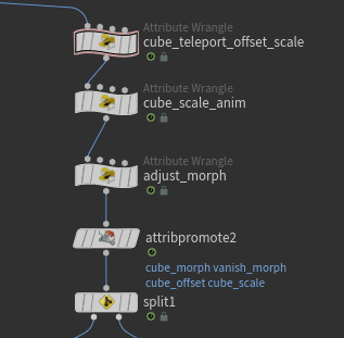
First, in cube_teleport_offset_scale, I set the cube_scale and cube_offset. The animation starts with a tall cube falling from the top and gradually transforming into a regular cube, so I animate the values accordingly.
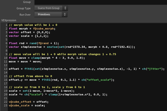
In this case, since the effect is to revert from the deformed state to the original, the morph value changes from 1 to 0. The move value, which controls the size of the offset and scale, changes from 1 to 0 as morph transitions from 1 to 0.75. This means that during the first quarter of the animation, the cube falls back to its original position.
For the scale, the y value animates from a larger value to 1, while the xz values animate from 0 to 1, giving the effect of a tall cube gradually becoming a regular cube.
I also introduce some noise to add variation to the animation.
Next, I want to animate the size slightly during the brief period before the falling cube transforms back into a triangle, similar to Example 2. I do this by adjusting the cube_scale with cube_scale_anim.
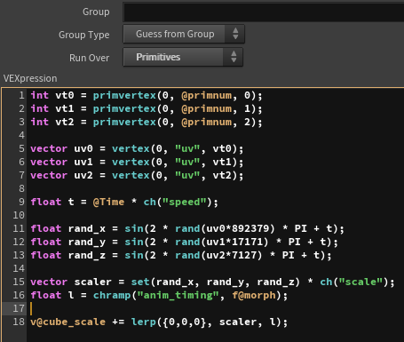
Since the implementation is quite similar to Example 2, I’ll skip the details, but essentially, after the cube finishes falling, I control the timing of the animation with a ramp.
I also control the timing of the deformation using the ramp, ensuring that the cube smoothly transitions back into the original triangle at the right moment.
Finally, I apply the triangle and cube deformation processes to each primitive.
Visual Adjustments
I won’t go into detailed explanations regarding the visual adjustments, so if you’re interested, please check the data I provide below.
https://heyyohanashima.gumroad.com/l/svdbo
Here, I’ll just provide a brief overview.
I directly edited the materials inside the rubbertoy, adding only the emission values. Essentially, I used uv2 and other attributes to create emission effects around the edges of the square and cube faces. For the voxel teleport, I set the entire surface to emit when the object first falls.
The control of the emission values is also handled by adjusting the morph value using a ramp.
For the glow effect, I applied it in post-processing using Houdini’s compositing tools. Since I didn’t know a good way to extract only the emission areas, I used a LumaMatte to isolate the high-luminance areas, applied a blur, and added the glow effect that way.
Conclusion
My first impression is that it’s “heavy!” haha.
If I had implemented this in Unity using Geometry Shader, it would have run smoothly in real-time, but it took about 15 minutes just to cache 180 frames…
However, one thing I like about Houdini is that it works exactly as written. When you implement it in Geometry Shader, there are often parts that become black boxes and aren’t as clear. In contrast, Houdini follows the instructions precisely, which makes implementation much easier.
Ultimately, the key is how you animate the parameters. For this example, I simply borrowed the ideas that Keijiro-sensei had already developed, so moving forward, I’d like to see what variations I can come up with on my own. Whenever I feel like it, I’ll challenge myself to explore new possibilities.