Epic Games distributes a project called “Content Examples,” which is a collection of various sample projects showcasing different features of Unreal Engine. Since UE4.26, there is a map called Niagara Advanced.
This map contains a wealth of useful samples, including examples of new Niagara features and practical applications. Upon reviewing the implementations, there’s a lot to learn.
This article will break down these samples into multiple parts for detailed explanations.

By the way, Content Examples can be downloaded from this link in Fab. Please note that the content may vary depending on the version of UE.
※Note: This blog is written based on UE4.26 Contents Example, so it might differ from the latest version in small details, but the concept itself explained here won’t change.
TLDR;)
- With Neighbor Grid3D, you can find the Index or ID of nearby particles.
- The basic usage of Neighbor Grid3D is as follows:
- Define a 3D grid.
- Write the ID or Index in the cell where your (Particle’s) position is located.
- Retrieve the ID or Index stored in the cell where your particle is located, as well as in the neighboring cells.
- Use the Particle Attribute Reader to obtain and utilize information about the particle corresponding to that ID/Index.
Introduction
This article will explain Neighbor Grid3D. Although the feature itself has been available since version 4.25, many samples were added to the “Content Examples” starting from version 4.26.
From those samples, we will focus on and explain the following three: “3.1 Color Copy by Cell」”, “3.2 Dynamic Grid Transform”, “3.3 Max Neighbors Per Cell”.
Additionally, when using Neighbor Grid3D, you will typically use it in conjunction with the Particle Attribute Reader and the Simulation Stage. If you’re unfamiliar with these, it’s recommended that you read the following articles first.
What is Neighbor Grid3D?
Before diving into the detailed explanation, let’s briefly summarize the concept.
With this feature, you can define a 3D grid of arbitrary size and store the Particle ID or Execution Index in each cell of the grid.
For example, if you define a 3x3x3 grid, there could be particles with IDs 2, 15, 98 in the cell (1, 0, 0), and particles with IDs 12 and 101 in the cell (2, 2, 2).
This allows you to know the IDs of particles that are stored in the cell where your particle is located or in its neighboring cells (i.e., nearby particles). If you know the IDs, you can use the Particle Attribute Reader to fetch information like color and other attributes of those particles.
Currently, this feature is only supported in GPU simulation.
Now, let’s look at the specific implementation.
3.1 Color Copy by Cell
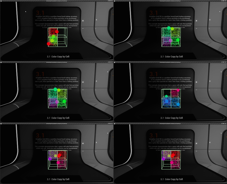
This sample involves both large and small particles. The large particles are randomly placed with random colors, and the small particles are generated at random positions. They then find the nearest large particle within the same cell (if there are multiple, the closest one) and copy its color.
The light green box visualizes the 2x2x2 Neighbor Grid3D, which is implemented within the same Niagara System. However, this visualization is not directly related to the core explanation, so we will not discuss it here.
Let’s first look at the part where Neighbor Grid3D is defined.
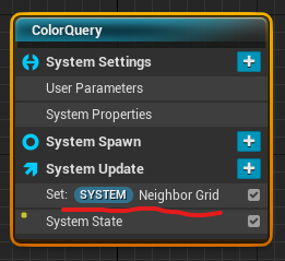
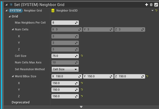
It is defined in the System Update, as it will be used by multiple Emitters. Since it is defined in the Update, it gets rebuilt every frame.
The “Max Neighbors Per Cell” refers to the number of particles that can be stored in each cell. We’ll look at this in more detail in section 3.3 “Max Neighbors Per Cell.”
Before we proceed, let’s first explain the “Set Resolution Method.” There are three options available in the dropdown: Independent, Max Axis, and Cell Size. Independent corresponds to Num Cells, Max Axis corresponds to Num Cells Max Axis, and Cell Size corresponds to Cell Size. The other options are disabled based on your selection.
This setting determines the number and size of the cells. Num Cells directly defines the number of cells in each dimension, and the cell size is determined by dividing the World BBox Size by the number of cells. Conversely, if you select Cell Size, the cell size is defined, and the number of cells is determined by dividing the World BBox Size by the cell size. Max Axis appears to correspond to setting the number of cells in the dimension with the largest World BBox Size, which then determines the cell size.
In this example, a 2x2x2 grid with each side length of 75 is defined.
Next, let’s look at the Emitter for the large particles, which will store information in the Neighbor Grid3D.
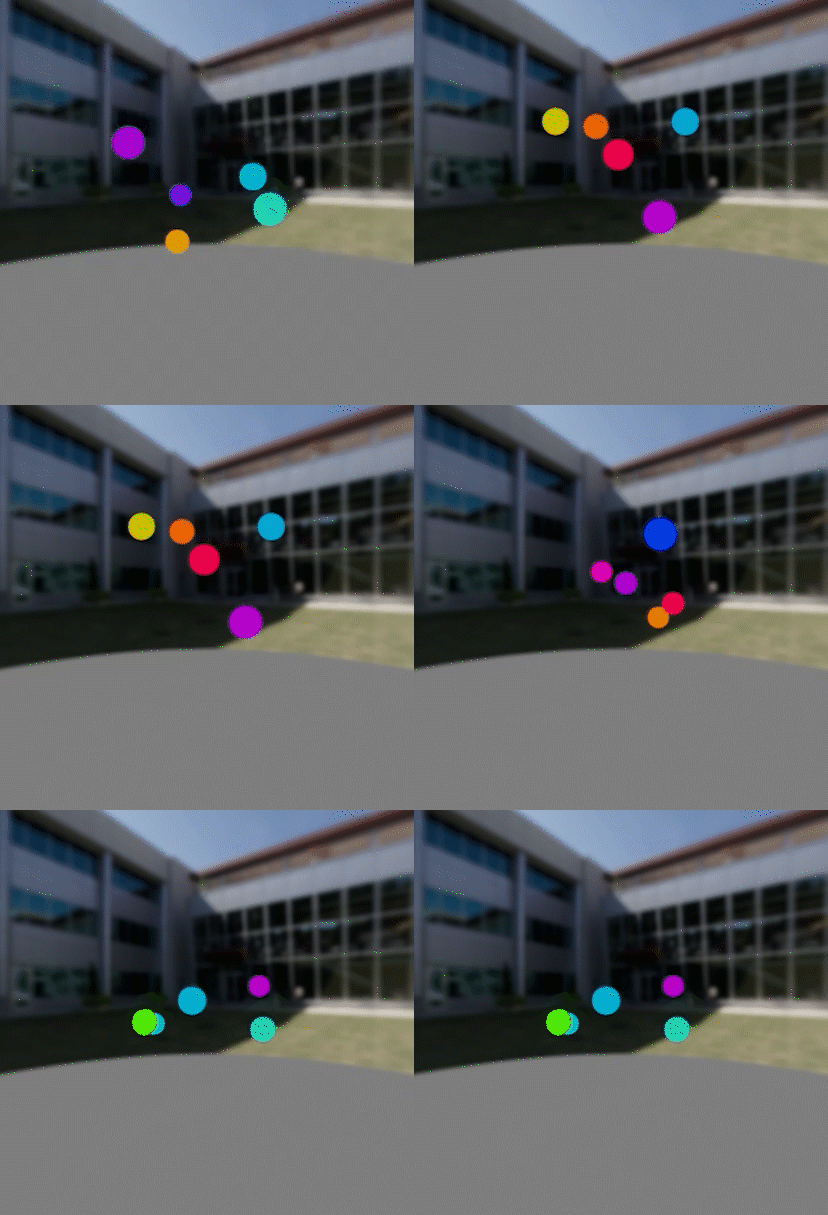
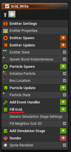
The particles are placed at random positions inside a box and with random colors using the Box Location module.
The key point here is that the “Fill Grid” Simulation Stage is used. The Iteration Source is set to “Particle,” so the process runs for every particle. The process itself is implemented with the “Fill Neighbor Grid 3D” Scratch Pad module, which writes the Execution Index of the particle into the appropriate cell in the Neighbor Grid3D.
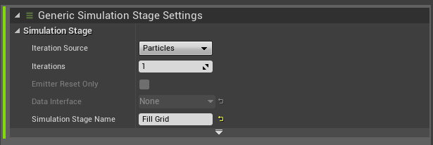
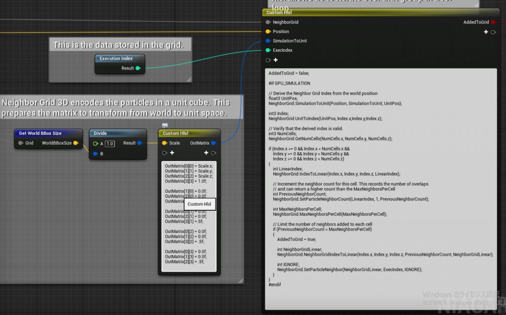
The processing is primarily done in HLSL, and I will provide a brief explanation with comments on the HLSL code.
// Result of whether the particle was successfully added to the grid
AddedToGrid = false;

// Ensuring that it's GPU simulation
#if GPU_SIMULATION

// Convert the particle's world position to the Neighbor Grid3D coordinate system (explained later)
float3 UnitPos;
NeighborGrid.SimulationToUnit(Position, SimulationToUnit, UnitPos);

// Get the 3D index of the cell from the UnitPos
int3 Index;
NeighborGrid.UnitToIndex(UnitPos, Index.x, Index.y, Index.z);

// Get the number of cells in the Neighbor Grid3D
int3 NumCells;
NeighborGrid.GetNumCells(NumCells.x, NumCells.y, NumCells.z);

// Ensure the index is valid
if (Index.x >= 0 && Index.x < NumCells.x &&
    Index.y >= 0 && Index.y < NumCells.y &&
    Index.z >= 0 && Index.z < NumCells.z)
{
    // Convert the 3D index to a linear index
    int LinearIndex;
    NeighborGrid.IndexToLinear(Index.x, Index.y, Index.z, LinearIndex);

    // Get the number of particles in this cell and increment it
    int PreviousNeighborCount;
    NeighborGrid.SetParticleNeighborCount(LinearIndex, 1, PreviousNeighborCount);

    // Get the maximum number of particles that can be stored in the cell
    int MaxNeighborsPerCell;
    NeighborGrid.MaxNeighborsPerCell(MaxNeighborsPerCell);

    // If the number of particles in the cell is less than the max, store the particle's info
    if (PreviousNeighborCount < MaxNeighborsPerCell)
    {
        AddedToGrid = true;

        // Get the index of the particle in the cell's array
        int NeighborGridLinear;
        NeighborGrid.NeighborGridIndexToLinear(Index.x, Index.y, Index.z, PreviousNeighborCount, NeighborGridLinear);

        // Save the Execution Index at the specified position
        int IGNORE;
        NeighborGrid.SetParticleNeighbor(NeighborGridLinear, ExecIndex, IGNORE);
    }
}
#endif
I think most of it can be understood by reading the comments, but I will provide an explanation for one point, which I indicated as “to be explained later.”
The function NeighborGrid.SimulationToUnit(Position, SimulationToUnit, UnitPos) converts the world position of the particle into the Neighbor Grid3D coordinate system (with values between 0 and 1).
Here, Position is the world position of the particle, and SimulationToUnit appears to be a matrix created using the World BBox Size of the Neighbor Grid3D. This is a standard code pattern, so you can likely copy and paste it.
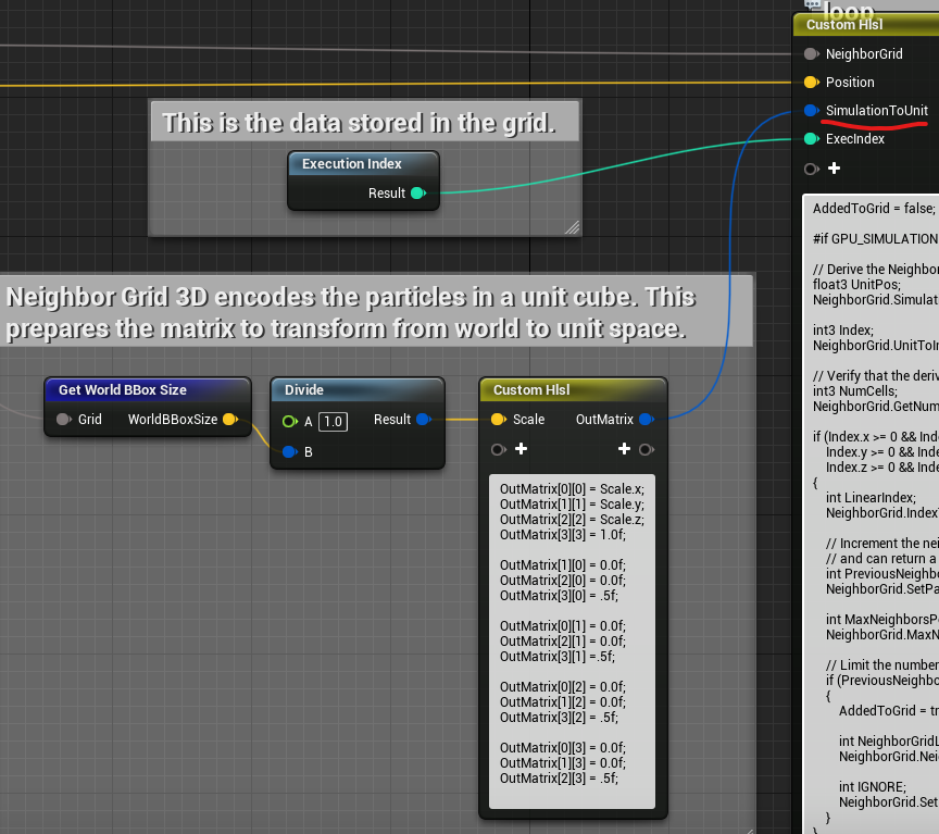
This allows us to store the Execution Index of the large particle in the grid.
Next, let’s look at the Emitter that searches the grid for the nearest large particle and copies its color.
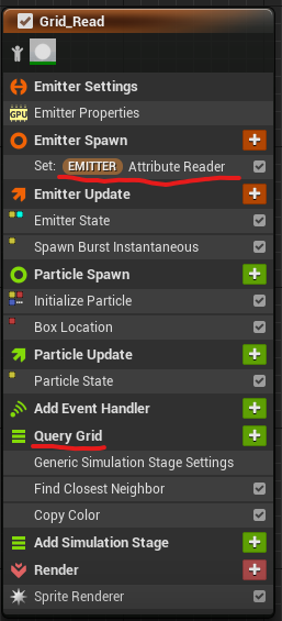
Key modules to note are the “Particle Attribute Reader” and the “Query Grid” Simulation Stage.
For the Particle Attribute Reader, the target particles are the large particles, so the Emitter Name is set to “Grid_Write.”
“Query Grid” uses the particles as the Iteration Source, and the process involves two Scratch Pad modules.
In “Find Closest Neighbor,” the closest large particle in the same cell is found, and its Execution Index is retrieved. Then, using this, the color is copied in the “Copy Color” module.
Let’s look at “Find Closest Neighbor” in more detail.
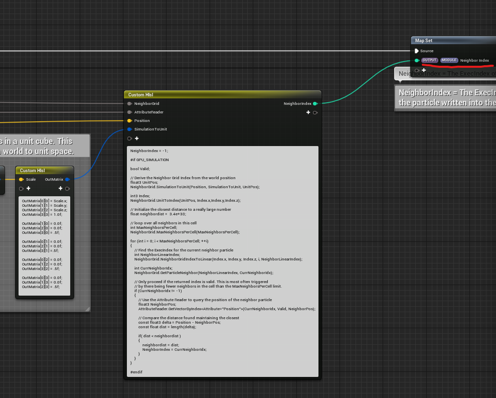
This too is written primarily in HLSL. At the end, the retrieved Execution Index is written to the Neighbor Index attribute.
Here’s the explanation of the HLSL code, with comments:
// The Execution Index of the closest particle is stored here. If no particle is found in the same cell, it outputs -1.
NeighborIndex = -1;

#if GPU_SIMULATION

bool Valid;

float3 UnitPos;
NeighborGrid.SimulationToUnit(Position, SimulationToUnit, UnitPos);

// Get the 3D index of the particle's cell
int3 Index;
NeighborGrid.UnitToIndex(UnitPos, Index.x, Index.y, Index.z);

// Initialize the closest distance with a very large value
float neighbordist = 3.4e+38;

int MaxNeighborsPerCell;
NeighborGrid.MaxNeighborsPerCell(MaxNeighborsPerCell);

// Loop through the maximum number of neighbors in the cell
for (int i = 0; i < MaxNeighborsPerCell; ++i)
{
    int NeighborLinearIndex;
    NeighborGrid.NeighborGridIndexToLinear(Index.x, Index.y, Index.z, i, NeighborLinearIndex);

    // Get the Execution Index of the neighbor particle
    int CurrNeighborIdx;
    NeighborGrid.GetParticleNeighbor(NeighborLinearIndex, CurrNeighborIdx);

    // If no neighbor is found (Execution Index is -1), skip
    if (CurrNeighborIdx != -1)
    {
        // Retrieve the position of the neighbor particle using the Particle Attribute Reader
        float3 NeighborPos;
        AttributeReader.GetVectorByIndex<Attribute="Position">(CurrNeighborIdx, Valid, NeighborPos);

        // Compare the distance to find the closest particle
        const float3 delta = Position - NeighborPos;
        const float dist = length(delta);

        // If a closer particle is found, update the Execution Index
        if( dist < neighbordist )
        {
            neighbordist = dist;
            NeighborIndex = CurrNeighborIdx;
        }
    }
}

#endif
Now we have retrieved the Execution Index of the closest large particle in the same cell and stored it in the Neighbor Index attribute. If there are no large particles in the same cell, it holds -1.
Finally, the color copy process is straightforward, using the Particle Attribute Reader to read the color and copy it.

This concludes the explanation of this sample. Writing to and reading from the grid is the basic usage of Neighbor Grid3D.
3.2 Dynamic Grid Transform
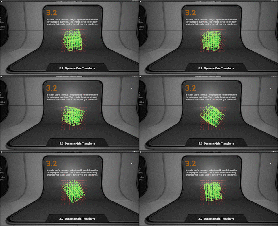
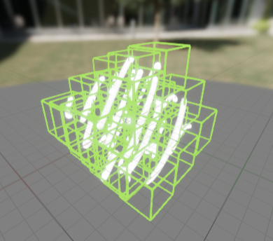
In this sample, a light green grid visualizing the Neighbor Grid3D continuously rotates, and the red particles arranged on the grid expand slightly and turn green when they enter the Neighbor Grid3D. This demo demonstrates this behavior.
Essentially, this is a sample showing that you can rotate the Neighbor Grid3D, and I will quickly explain how it works.
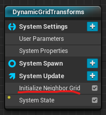
This time, we initialize the Neighbor Grid3D within the System Update, but unlike the previous example, we use the “Initialize Neighbor Grid” node. By using this node, we can set the position and rotation of the grid.
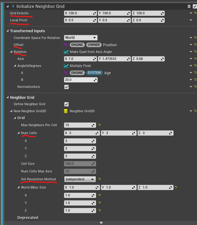
You can adjust the size with Grid Extents and set the pivot position with Local Pivot. I experimented a bit, but it seems like only the Independent option works for the Resolution Method. In other words, by setting the Num Cells, you decide the number of cells in the grid.
With Transformed Inputs, you can set the position with Offset and rotation with Rotation. Here, it is set to rotate according to the Age on a specific axis, which allows for continuous rotation.
Another advantage of using Initialize Neighbor Grid is that it writes various grid-related information to Attributes.
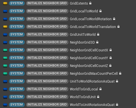
In fact, by using the WorldToGridUnit inside, we determine whether a particle is inside the Neighbor Grid3D or not.
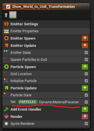
The emitter places the red particles on the grid. The placement is handled with the “Spawn Particles in Grid” and “Grid Location” nodes.
The expansion and color change to green when inside the Neighbor Grid3D is achieved using the DynamicMaterialParameter in the material.

We use “Transform Position by Matrix” to convert the particle’s position to a normalized coordinate within the Neighbor Grid3D using WorldToGridUnit. This means that if the particle is inside the grid, its value will range from 0 to 1 in each dimension. These values are then input into the DynamicMaterialParameter’s RGB.
Although I will skip the details, in the material, it checks if the RGB values from the DynamicMaterialParameter fall within the range of 0 to 1, and controls the color and size accordingly.
This concludes the explanation of this sample, but as a bonus, the material that visualizes the Neighbor Grid3D uses the unique “SplineThicken” node, so it might be interesting to check it out.
3.3 Max Neighbors Per Cell
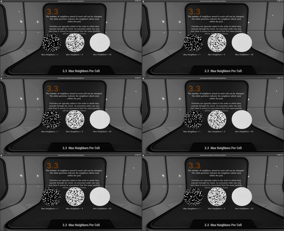
This sample demonstrates the behavior when Max Neighbors Per Cell is set, and shows that the execution order of the Simulation Stage’s Execution Index is random (changing every frame).
The content involves storing particles in the Neighbor Grid3D, and if the storage is successful, the particle turns white, while if it fails, it turns black. When Max Neighbors Per Cell is set to 1, only one particle can be stored in each cell, so storage fails in most cases (only the particle processed first in each cell succeeds), resulting in mostly black particles. However, when Max Neighbors Per Cell is set to 25, all particles can be stored successfully, and they turn white.
By observing the GIF image, you can see that the particles turning white are swapped out every frame. This is due to the fact that the order of the particles being processed each frame is different, as mentioned earlier. When using the Execution Index in the Simulation Stage, it’s important to keep this in mind.
Now, let’s look at the details.
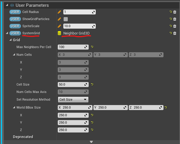
In this case, we are creating a Neighbor Grid3D as a User Parameter. After placing it in the level, you can set parameters like Max Neighbors Per Cell for each instance. Here, 100 is set arbitrarily.
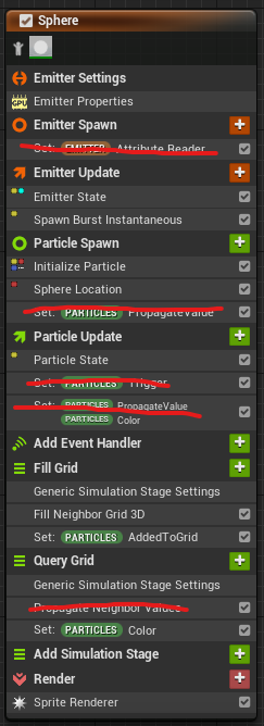
Next, for the emitter handling the process, not many modules are used.
This is because this Niagara System is also used in the “3.4 Color Propagation” sample. It is managed with the “ShowGridParticles” User Parameter flag to switch between the two.
In this sample, the functionality removed from the image is not used.
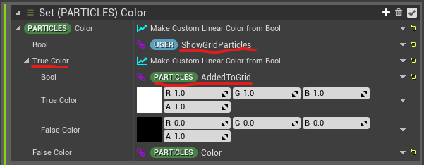
In the “Set Color” section, processing is divided based on the flag from ShowGridParticles. This sample corresponds to the “true” case, where the AddedToGrid attribute is used to color the particle white if true and black if false.
As the name suggests, AddedToGrid is a flag indicating whether the particle was successfully stored in the Neighbor Grid3D.
This flag is set within the Fill Grid simulation stage.

It simply binds the output attribute of Fill Neighbor Grid 3D. Since Fill Neighbor Grid 3D is a Scratch Pad module, let’s take a look inside.
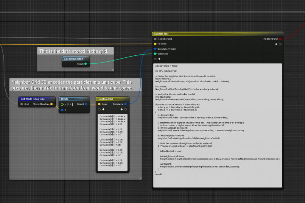
We’ve seen this before. Yes, it’s exactly the same as Fill Neighbor Grid 3D in “3.1 Color Copy by Cell.” In the “3.1 Color Copy by Cell” example, there was a filter processing based on the value of Max Neighbors Per Cell.
Conversely, this means that it’s only being filtered inside HLSL, so if you try to save more particles than the limit, it seems like you could do that, but performance might degrade.
Anyway, this concludes the explanation of this sample. The “3.4 Color Propagation” part would be explained in a separate article.
Conclusion
The functionality to search for particles near you has a wide range of applications, and it’s also used in Position Based Dynamics, which I will explain next.
At its core, it involves reading and writing to a grid, and the processing is mostly boilerplate code, so it might eventually become a default module. However, knowing how it behaves internally can be very useful, so I hope this article was helpful.
Enjoy your CG life!


