Epic Games distributes a project called “Content Examples,” which is a collection of various sample projects showcasing different features of Unreal Engine. Since UE4.26, there is a map called Niagara Advanced.
This map contains a wealth of useful samples, including examples of new Niagara features and practical applications. Upon reviewing the implementations, there’s a lot to learn.
This article will break down these samples into multiple parts for detailed explanations.
By the way, Content Examples can be downloaded from this link in Fab. Please note that the content may vary depending on the version of UE.
TLDR;)
- The Simulation Stage is like a “Particle Update that can iterate within a single frame.
- The Simulation Stage can process not only particles but also specific Data Interfaces.
- The Simulation Stage is a fundamental feature, so how you use it is what matters.
Introduction
In this article, I will provide a basic explanation of a new feature called Simulation Stage added since UE4.26, based on the “1.1 Simulation Stage Fill Render Target” sample from Niagara Advanced.
The Simulation Stage is a core feature used in many other samples in Niagara Advanced. The concept itself is simple, but its use cases are important. First, let’s focus on understanding what the Simulation Stage is.
※ Note: this article is written with UE4.26 Content Example data. So it might differ from the latest version of UE at some point, but the basic concept of the Simulation Stage must be the same.
What is the Simulation Stage?
Simply put, the Simulation Stage is “a Particle Update that can iterate multiple times within a single frame.” It allows you to run the specified process multiple times within one frame.

Before UE4.26, iterating processes required writing HLSL code inside the Scratch Pad or using the experimental “Map For” node. Now, this is much simpler to implement, and it is even possible to use existing Particle Update modules within iterative processes.
What’s innovative about the Simulation Stage is that it allows not only Particle updates but also processing on specific Data Interfaces, such as a 2D Render Target.
Although we don’t yet know all the possible Data Interfaces, such as Grid2D Collection, that can be used in this context, the potential seems infinite depending on the types of Data Interfaces available.
For Unity users, this might feel somewhat similar to how Compute Shaders are implemented in Visual Effect Graph, but note that they are GPU-accelerated and can only be used in GPU Sim mode.
Now that we’ve covered the concept of the Simulation Stage, let’s take a look at a specific example from the Niagara Advanced “1.1 Simulation Stage Fill Render Target” sample to understand it better.
At a glance, here are the key points to remember about the Simulation Stage:
- It allows for repeated processing within a single frame.
- It can be used to process not only particles but also specific Data Interfaces.
- It is only available in GPU Sim mode.
1.1 Simulation Stage Fill Render Target Explanation

This is the first sample in the Niagara Advanced map.
At first glance, it may seem like just a Sprite with a Texture applied, but internally, it uses the Simulation Stage to fetch the color of each texel from the texture and write it to a 2D Render Target. This Render Target is then passed to a Material for rendering.
Let’s dive into the details.
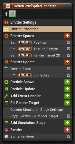
When you open the FillRenderTarget Niagara System, you’ll see an emitter called EmitterLevelSpriteRenderer. The setup is simple: it initializes several variables and performs processing in a single Simulation Stage.
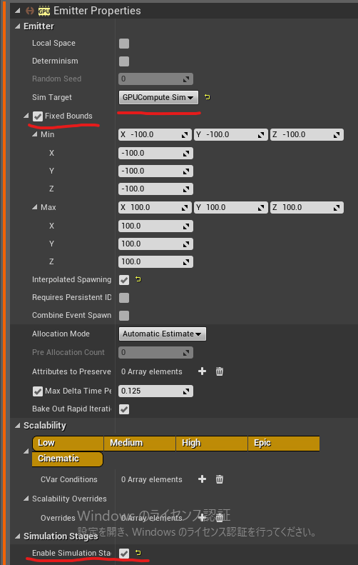
To enable the Simulation Stage, switch to GPU Sim in the Emitter Properties, check Fixed Bounds, and also check Enable Simulation Stages (Experimental GPU Only) under the Simulation Stages section.

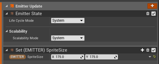
The Emitter Spawn and Emitter Update initialize the Position, Texture Sample, Render Target 2D, and Sprite Size. The Sprite Size is initialized in Emitter Update, but it could also be done in Emitter Spawn without issue.
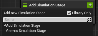
To add the Simulation Stage, click the plus sign next to Add Simulation Stage and choose Generic Simulation Stage.
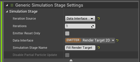
In the Iteration Source dropdown, you can select either Particle or Data Interface. Since this example involves writing to a Render Target 2D, you choose Render Target 2D as the Data Interface.
Iterations defines the number of iterations to perform.
Check Emitter Reset Only if you want the processing to occur only during the first frame when the Emitter is reset.
The name you enter in Simulation Stage Name will appear as the stack’s name.
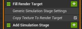
Copy Texture To Render Target is just a renamed Scratch Pad module. Let’s double-click to explore its contents.
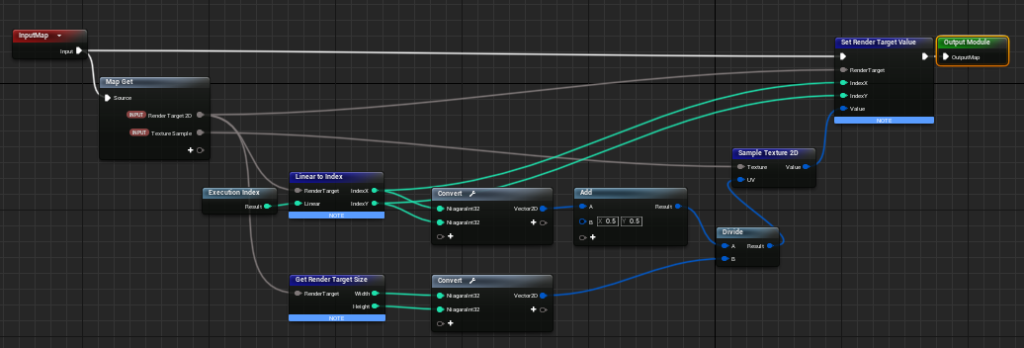
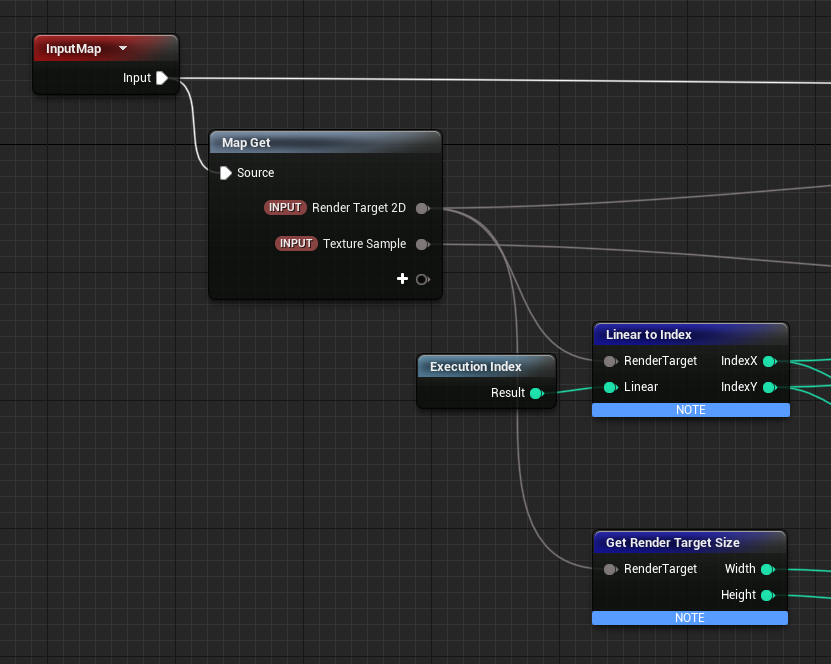
The inputs are Render Target 2D and Texture Sample. Here, the important part is the Execution Index. Since we’ve set Render Target 2D as the Data Interface, the Execution Index corresponds to the texel index of the 2D Render Target. Since we initialized the Render Target 2D with a 512×512 size, the Execution Index will range from 0 to 262,143.
We then use Linear to Index to map the 0-262,143 range into 2D indices like (0,0), (0,1), (511,510), and (511,511).
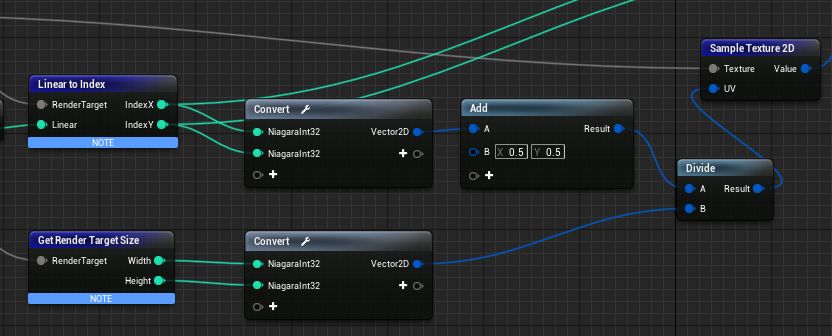
Next, we use Get Render Target Size to obtain the width and height of the 2D Render Target, and divide the 2D indices to convert it into UV values ranging from 0 to 1 (Although (0.5, 0.5) is added, this is incorrect, so it’s more accurate without it. It’s just a small error, so it shouldn’t cause much of an issue).
Then we sample the texture at those UV values using Sample Texture 2D to retrieve the color information of each texel.
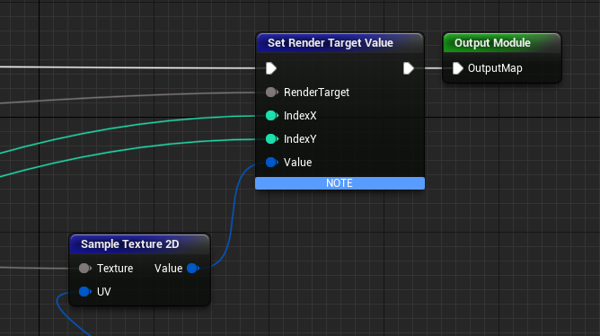
Finally, the color information is written back to the corresponding texels of the Render Target 2D.
At this point, the Texture Sample has been successfully copied to the Render Target 2D.
Next, this Render Target 2D is passed to a Material, but there’s a new feature in UE4.26 related to this.
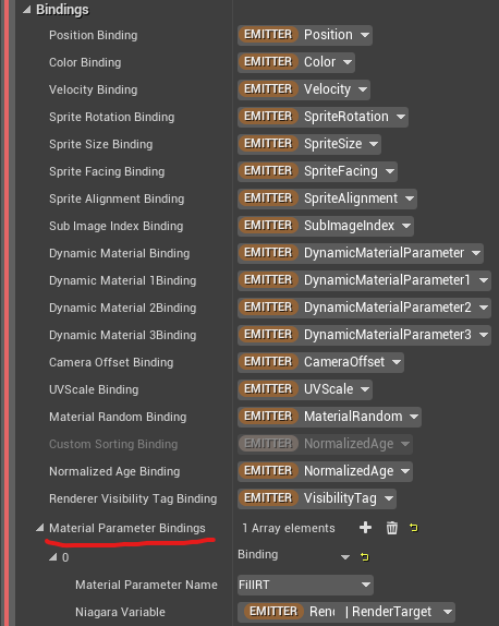
In the Sprite Renderer’s Bindings section, you’ll see an option called Material Parameter Bindings. This allows you to assign values to parameters exposed by the Material.
You might think, “Does this mean we don’t need Dynamic Parameters anymore?” However, it seems that this can only be used for Emitter or System attributes, so if you want to change values per Particle (like per-particle color), you’ll still need to use Dynamic Parameters.
In any case, here we use it to pass the Render Target 2D to the Material. The Material’s processing is straightforward, as it simply displays the received texture.
Now, one thing we haven’t discussed yet is why the sprite is displayed even though no particles are emitted. This is another new feature in UE4.26: you can now display particles based on Emitter information.

If you look closely, you’ll see that the number of particles is set to 0.

By changing the Source Mode in the Sprite Renderer to Emitter, the bindings will use Emitter attributes, allowing you to spawn a single particle based on those attributes. This is why the Emitter’s attributes, like position and sprite size, were initialized earlier in the process.
Bonus
The Simulation Stage Fill Render Target example might seem trivial, but I will demonstrate an example of how easily certain tasks can be achieved with the Simulation Stage.
By simply reducing the size of the Render Target 2D from 512×512 to 32×32, you can instantly get a pixel-art-like appearance.

This is just one of the ways you can manipulate and display original images using the Simulation Stage. By combining it with Grid2D Collection, you can perform even more complex operations. I’ll go over that in a future article.
Conclusion
This concludes our explanation of the Simulation Stage. It’s a core feature of Niagara’s new functionality, and I personally think it’s quite innovative.
In future articles, I’ll go into more detail on its use in 2D fluid simulations, Position-Based Dynamics, Neighbor Grid 3D, and more. The possibilities are endless depending on how you approach it, so I encourage you to experiment and explore the many applications yourself!


